Kurz 155 Guide de l'utilisateur

Kurz Instruments, Inc. 831-646-5911
2411 Garden Road www.kurzinstruments.com
Monterey, CA 93940
Start Up Guide
Models 155, 454FTB, 504FTB, and 534FTB.
December 2007
155 Line
MFT B-Series
360208-D Models 155, 454FTB, 504FTB, 534FTB 1

Kurz Instruments, Inc. 831-646-5911
2411 Garden Road www.kurzinstruments.com
Monterey, CA 93940
The following information is an abbreviated list of what you need to do for your flow
meter to achieve maximum possible repeatability and accuracy. Most of the steps will be
required for all products. Please read this before you start.
You will ultimately need to refer to the product manual, which is found on the attached
CD. Given the Model number of your product, you can find the manual you require.
+ Kurz Model # =
Unpacking/Expected Content
Your flow meter has been shipped to you with the following items. Please make sure you
have them and contact us if this is incomplete.
1. Flowmeter, compare the packing list against your order.
2. Calibration certificate
3. Flow Computer Input Configuration Sheet (155 only)
4. Manual on CD
Mounting of the equipment (see guidelines sheet)
You will need to remove the protective shipping covers from the sensor or flowbody
before installing the unit. A thermal meter must have direct contact with the process fluid
to work. The meter will need to be mounted in accordance to safe design practice
accounting for the process pressures, corrosion, temperature and any potentially
hazardous area requirements. The electronics head needs to be in an accessible area so
you can do the wiring and access local keypad LCD if applicable. Some models have
remote electronics heads, which must be mounted/wired too. Most units can be
programmed with a Laptop portable computer using the USB interface and PC driver.
For best results, please carefully look over the installation guidelines sheet for more on
the sensor placement criteria.
Insertion Meters must be mounted with a compression fitting to the duct/pipe or flange
mounted then checked for leaks. Make sure the insertion depth is adequate to get into the
center 1/3 of the diameter where the flow profiles are the most stable. The distance from
profile disruptions needs to be adhered to for the best repeatability/accuracy, see the
guideline sheet for more details.
In-Line Meters have similar requirements for undisrupted straight runs except for the
534FTB line. Check for process fluid leaks.
360208-D Models 155, 454FTB, 504FTB, 534FTB 2

Kurz Instruments, Inc. 831-646-5911
2411 Garden Road www.kurzinstruments.com
Monterey, CA 93940
360208-D Models 155, 454FTB, 504FTB, 534FTB 3
>
X
Vavg
Vs
CF(v) ?
CF(v)= Vavg/Vs
0.5 < CF(v) < 1.0
Kurz 4xx (454,etc.)
D
A ? (ft2or m2)
A = D2π/4
d
L
L ? (ft, m), d ? (in)
SBCF= A/(A+12dL)
>
5D
CF(v)
v
x
x x x
0.7
1.0
Vs
< 2%
Less than two line
size changes
ε
Less than two line
size changes
20D
=
40D
X
15D
=
X
=
X

Kurz Instruments, Inc. 831-646-5911
2411 Garden Road www.kurzinstruments.com
Monterey, CA 93940
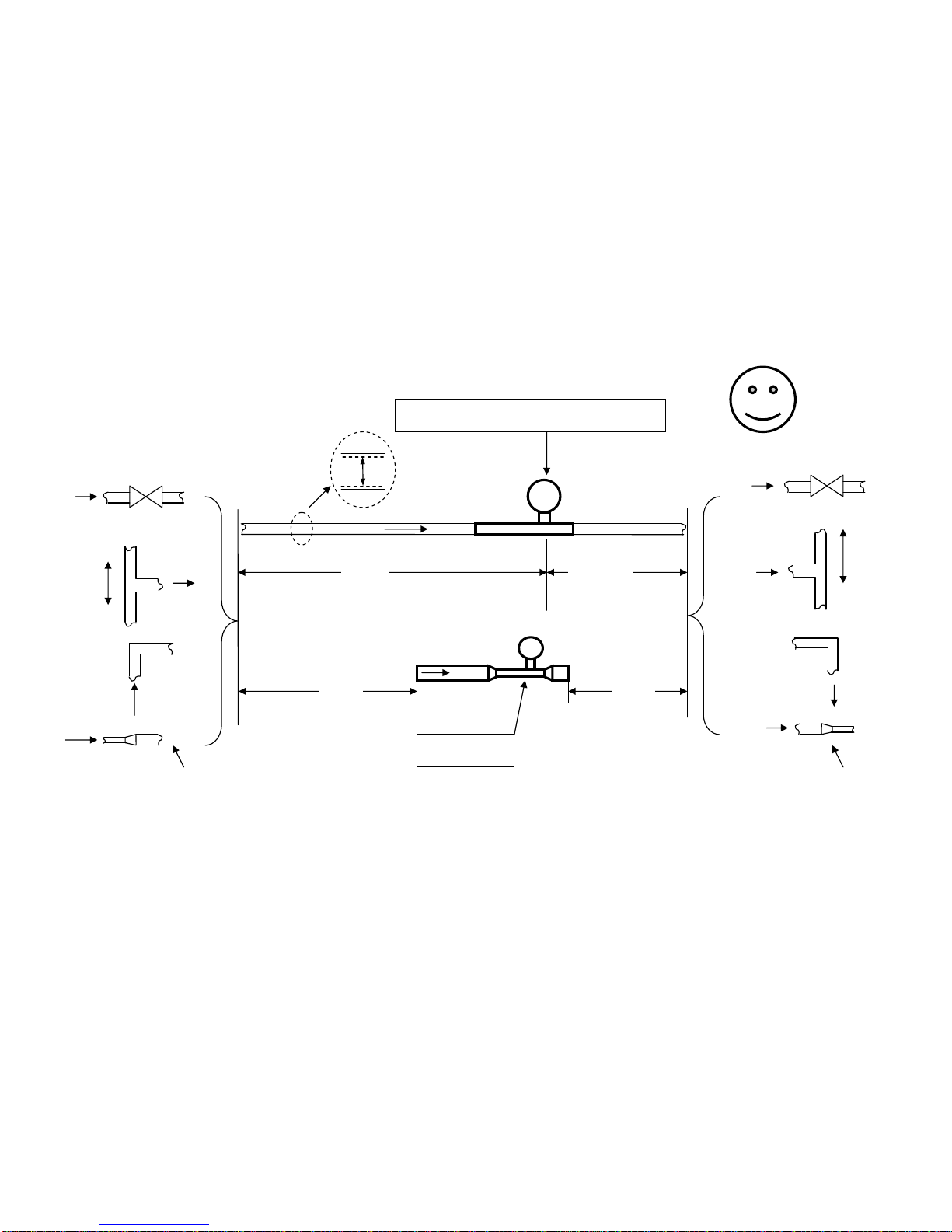
Insertion Meter Installation Guidelines
1. Mount Probe so its velocity sensing element is centered in the duct/pipe. This location has the most stable flow reading. Note the flow arrow direction
points in the direction of the flow.
2. The upstream and downstream distance to flow profile disruptions from that of a straight pipe are “X” diameters upstream and 5 downstream. We have
chosen 2% maximum error from the baseline straight pipe calibration for the distance criteria. Longer straight runs will reduce this error level. Here are
four example cases in order of their disruption to the flow:
a. Valves change the flow profile as they open and close so the sensor should not be located too close. The gate valve is the worst and the metering
valves are the best at reducing their flow profile changes between open and closed.
b. Branching joints also change the profile as the percentage of flow changes between the branches.
c. Elbows or direction changes will disrupt the long-run pipe profile. As this disruption settles down, the profile can wobble or move depending on
the flow rate. Several elbows in different planes will impart a swirl that also imparts an error in the readings (flow is not straight on to the sensor)
and the upstream distance should be increased. The distance from elbows may be reduced if field calibrations are used. Double elbows in different
planes introduce swirl and need 50% more distance than a single elbow does.
d. A line size change will also disrupt the profile and can introduce instability so this should be avoided unless you have more experience on how to
use this to your advantage. The distance from a line size change may be reduced if field calibrations are used.
3. The duct area or pipe inside dimensions are used to program the area of the flow meter. You enter the data in ft2or m2in the Program Mode of the meter.
4. The probe will block off some of the flow area and accelerates the velocity proportional to its area projected on to the duct/pipe cross section. This is known
as the Sensor Blockage Correction Factor (SBCF) and is simply defined by entering the insertion depth (L) from the end of the window to the duct inside
wall and specifying the diameter (d) of the probe in the Program Mode of the meter.
5. Field Calibration Data is the key to achieving accuracy for the insertion probe. Without this step you can have good repeatability but the absolute flow
number requires a reference flow measurement be taken at the same time you record the indicated display of the insertion meter. The correction factor
which is velocity dependent, CF(v), is defined as the ratio of True reading to Indicated reading. The basic calibration of the unit is a point velocity sensor.
To convert this to volumetric flow rate or mass flow rate requires the proper area and the average velocity, this is where the field calibration fits in. As the
field calibration method is quite long and technical, you are encouraged to do one of two things to achieve this:
a. Contract the field calibration with Kurz Instruments, Inc. or another reputable field calibration company.
b. Do it yourself if you have the experience or a test team at your disposal.
Common methods of doing reference method calibrations entail: duct traverses, tracer gas dilution method or the process Stoichiometry which requires support
from your process engineering group. Sometimes the correction factors can be entered based on an ideal duct profile model or a finite element analysis (FEA) or
computation fluid dynamics (CFD) program.
For more information on all the above, please refer to the full product manual provided on CD or at our website www.kurz-instruments.com. Also see “Flow
Measurements 2nd ed.” Edited by D. W. Spitzer, ISA Press 2001. Chapter on Insertion Flow Measurements.
360208-D Models 155, 454FTB, 504FTB, 534FTB 4
Kurz Instruments, Inc. 831-646-5911
2411 Garden Road www.kurzinstruments.com
Monterey, CA 93940
360208-D Models 155, 454FTB, 504FTB, 534FTB 5
< 2%
ε
Kurz 5xx (504 etc.)
>
X
D
>
5D
Kurz 534
0D
X
=
40D
X
=
20D
0D
X
=
15D
Less than two line
size changes
Less than two line
size changes

Kurz Instruments, Inc. 831-646-5911
2411 Garden Road www.kurzinstruments.com
Monterey, CA 93940
In-Line Meter Installation Guidelines
1. Mount the Meter so its sensing element meets the upstream and downstream requirements of that model:
a. Kurz Models 504 etc. all need “X” inside pipe diameters upstream and 5 downstream of the sensing element to ensure a
repeatable and accurate reading within 2% of the initial calibration. Double elbows in different planes introduce swirl and
need 50% more distance than a single elbow does. Longer straight runs will reduce this maximum error. Any
discontinuity in the straight pipe flow profile will change the reading compared to its calibration conditions. The data were
initially calibrated using long straight runs with short close-coupled pipe flanges that minimize the line-size discontinuity.
In many applications, field calibration data can be used to reduce the upstream and downstream requirements.
b. Kurz Model 534 have a built in flow conditioner and all the straight run it needs so there is no upstream or downstream
straight run requirements to achieve the rated accuracy.
2. If the process fluid is hot or cold compared to the ambient air, then insulation around the pipe/meter upstream for about 30
diameters or more will help reduce thermal gradients in the process fluid near the sensor to avoid these errors. As the temperature
is changed, the thermal inertia of the piping will cause a lag in the thermal profile so a longer stabilization time will be required.
For more information on all the above, please refer to the full product manual provided on CD or at our website www.kurz-
instruments.com
360208-D Models 155, 454FTB, 504FTB, 534FTB 6

Kurz Instruments, Inc. 831-646-5911
2411 Garden Road www.kurzinstruments.com
Monterey, CA 93940
360208-D Models 155, 454FTB, 504FTB, 534FTB 7

Kurz Instruments, Inc. 831-646-5911
2411 Garden Road www.kurzinstruments.com
Monterey, CA 93940
360208-D Models 155, 454FTB, 504FTB, 534FTB 8

Kurz Instruments, Inc. 831-646-5911
2411 Garden Road www.kurzinstruments.com
Monterey, CA 93940
360208-D Models 155, 454FTB, 504FTB, 534FTB 9
~ AC Power
454 [ Vdata, Area, CF(v) ]
°
°
Customer I/O
Panel
°
°
°
°
4-20 mA, AO = FLOW & Temp.
OR 2 or 4 Digital I/O
504/534 [Fdata ] 224 VDC
°
°
°
°
°
°
Customer I/O
Panel
~ AC Power
224-20 mA
,
velocit
y
24 VDC
454
[
V
data
,
]
4-20 mA, AO = FLOW
2
155 [ Area, CF(v) ]
•
•
•
•
Digital I/O
BASIC SETUP
OR
504/534 [Fdata ] REMOTE DISPLAY SETUP

Kurz Instruments, Inc. 831-646-5911
2411 Garden Road www.kurzinstruments.com
Monterey, CA 93940
360208-D Models 155, 454FTB, 504FTB, 534FTB 10
Wiring, Sensor, Power and Signals
The thermal flow meter uses several watts of power to measure flow, so it requires more
than a simple 4-20 mA loop powered connection for operation. In general our products
are know as a “4-wire” device, power (2) and signal (2 or 4). The exact wiring diagram
for your meter can be looked up on the provided CD manual using the model number of
the meter. The two AC and DC power examples (pages 7&8) for the single 4-20 mA
output on the B-Series assume the PLC is connected to a loop powered device.
Potentially Hazardous Area Use and EMI Compliance
Please consult the full manual on the provided CD for safety and EMI related issues.
Sensor
For “Remote Electronics” you need to run five wire cable for each sensor between the
sensor J-box and Flow Computer. The wire gage/length and conduit/shielding
requirements are found in the manual and on the field wiring diagrams. The transmitter
attached versions have no sensor wiring requirements.
I/O wiring
The image below is for the 155Jr. This is used on remote display versions of the product.
Analog
Outputs
RS-232
Sensor
Input
Cal/Operate
Switches
AC
Power
155Jr I/O board photo (155A/B,155C-2/E-2 are not shown).
Ce manuel convient aux modèles suivants
3
Table des matières
Autres manuels Kurz Instrument de mesure


Manuels Instrument de mesure populaires d'autres marques


Endress+Hauser
Endress+Hauser Proline Promag 50 Caractéristiques techniques

Siemens
Siemens SITRANS F Coriolis FCT030 Manuel de la liste des pièces

KLINGER
KLINGER CMF V Series Manuel utilisateur

EXFO
EXFO FTB-2 Manuel d'exploitation et d'entretien

Keysight
Keysight M8290A Manuel utilisateur

ADTEK
ADTEK MW-5 Manuel utilisateur