
Kurth KE3550 Manuel utilisateur

Version 17.05.01
© KURTH ELECTRONIC GmbH
All rights reserved, including translations.
All reprints and electronic copies, including excerpts, require prior written approval
of Kurth Electronic GmbH.
All of the brand names and trademarks cited herein are the property of their registered owners.
KE3550
xDSL M
ULTI
T
EST
Short Operating Manual
Kurth Electronic GmbH | Muehleweg 11 | D 72800 Eningen u.A. GERMANY |
Tel. +49(0)7121 9755 0 | Fax +49(0)7121 9755 56 |

© Kurth Electronic GmbH, All Rights Reserved
2
Application
The KE3550 is a fast, easy to use and aordable multitester for the instal-
lation and troubleshooting of DSL services in hybrid ADSL1 / 2 / 2+ / VDSL2
and combined networks. With its numerous interfaces, it supports the entire
range of broadband network technology such as Vectoring, G.fast, Bonding
and Gigabit Ethernet.
Operation
The KE3550 is a powerful troubleshooting tool for quickly nding faults in the
network, outside wiring, customer devices or inside wiring. Because of this,
the KE3550 is the ideal solution for all broadband technologies.
Use
With its small size, robust design and intuitive operation, it is the perfect
tester for installers and service technicians. The user can perform his tasks
quickly and eciently with automatic detection of the xDSL service and de-
nable test procedures. The large display increases operating convenience
and, when storing results, the technician has numerous options for exporting
the tests and for compiling reports.
At a glance
Multitasking tests without loss of synchronization
ADSL-VDSL2, G.fast and Bonding in one device
Annex A/B/J/L/M with automatic xDSL detection
DSL vectoring (ITU-T G.993.5)
Web browser
GbE port for expanded Ethernet tests
All DSL parameters at one glance
IP Ping, Traceroute with IPv4 and IPv6
HTTP / FTP up / download test up to 800 MBit/s
Sunlight viewable color TFT
High-power rechargeable battery and expandable memory
Includes Software for mangement and protocols
Bluetooth and Wi-Fi integrated
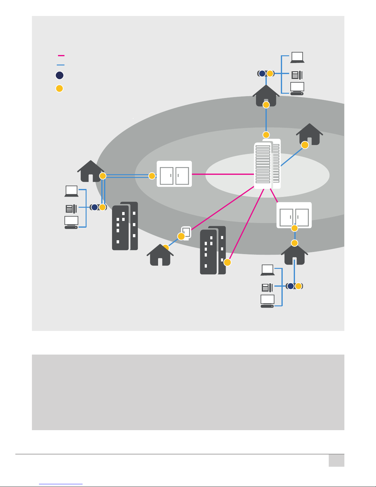
© Kurth Electronic GmbH, All Rights Reserved
3
Documentation and Software
Up-to-date operating instructions and software updates can be found in
our download area after logging on in the CUSTOMER LOGIN.
You will nd the download area for the KE3550 under the Downloads
menu item. After entering the serial number, you will nd all current docu-
ments available for download in the following window.
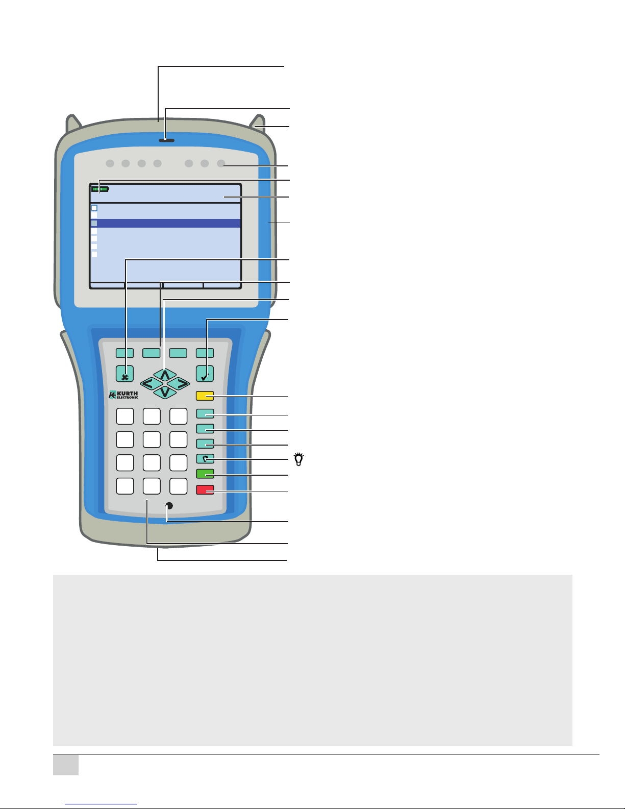
ADSL2+
~6-25 Mb/s
VDSL2
~50 Mb/s
CENTRAL
OFFICE
DSLAM Cabinet
FTTN
DSLAM Cabinet
VDSL2
VECTORING
~100 Mb/s
VDSL2
VECTORING
~100 Mb/s
VDSL2
G.fast
~500 Mb/s
VDSL2
BONDING
~100 Mb/s
Fiber
Copper
DSL Bonding
VDSL2
ADSL2+
xDSL Test
Ethernet Test
STB
STB
STB
TV
TV
TV
VoIP
VoIP
VoIP
PC
PC
PC
Applications
© Kurth Electronic GmbH, All Rights Reserved
4
F1 F2 F4F3
SEL
ESC
0
*#
12
ABC
3
DEF
4
GHI
5
JKL
6
MNO
7
PQRS
8
TUV
9
WXYZ
VIEW
VOL
SPKR
SHIFT
ON-OFF
HELP
DSL
CRC
DSL
LOSS
DSL
L1
DSL
L2
ETH
Link
USB2
Link
MGMT
Link
KE3550 xDSL M
ULTITEST
®
Schnittstelle
Hilfe
Datum / Uhrzeit
Breitband
a/b: 0,0 V
2
Endgeräte Modus
Router Modus
Modem Modus
4
5
6
<xDSL>
xDSL Schnittstelle
3
Profile laden und speichern
1
G.FAST
7
<Ein>
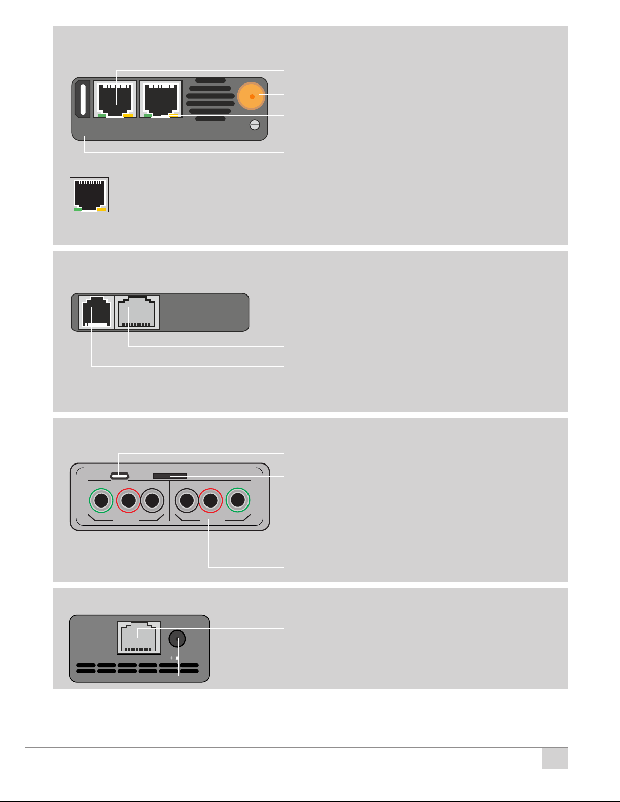
Keyboard / Display / Ports
Status LEDs
DSL CRC - orange > Indicates a CRC error
DSL LOSS - orange > Loss display with beep
DSL L1 - green >DSL connection established
DSL L2 - green > DSL line 2 connection established (bonding)
USB2 Link - green > Indicates active USB connection, e.g. when saving
ETH Link - green > Indicates active ethernet connection
MGMT Link - green > Indicates active connection: Management port to PC
Ethernet 10/100/1000 Management,
Ethernet 10/100/1000 Test port, USB 2
ISDN analogue interface, SFP port
xDSL test port, power supply connection
Fastener for shoulder strap
Status LEDs
Speaker (Telephony)
Battery indicator
Sunlight readable TFT colour display
Connection: USB 1, SD card
optional KECT interface
Menu-sensitive function keys F1 – F4
Menu UP- DOWN / LEFT- RIGHT buttons
ON / OFF button
Microphone (Telephony)
Alphanumeric keypad
ESC (back) button
Select (enter) button
Shift button: Function keys F5 – F8
View button: Back to main menu
Speaker button: Speakerphone
Vol button: Increase volume (3 levels)
button: Increase brightness (3 levels)
Help button: Open the help function
© Kurth Electronic GmbH, All Rights Reserved
5
USB 2
ETH 2
1000 Mb/MGMT
ETH 1
1000 Mb
POTS
ISDN-U
ISDN-S
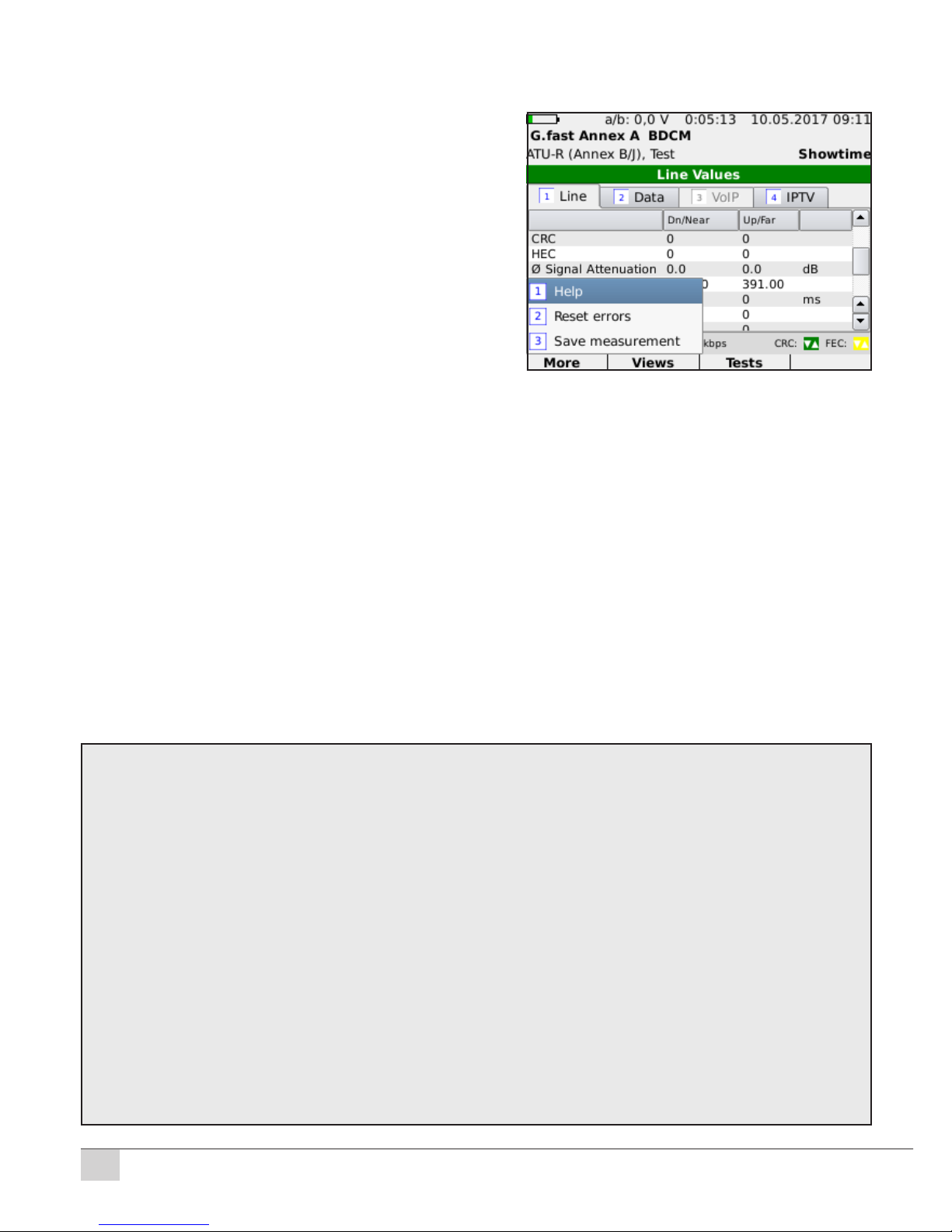
Upper side ports: Ethernet Ports
1 Gbit/s port for ethernet tests
10/100/1000 Mbit/s
Yellow LED: Link / Data
LED lights continuously: Connection has been established
LED ashes: Transmit / receive activity
Green LED: Transmission speed
USB 2: Function expansion
(e.g. external keyboard, USB storage)
Device management port
10/100 /1000 Mbit/s
Connection Wi-Fi antenna
Upper side ports (optional): ISDN (BRI)/Analogue (POTS)
RJ11 Analogue Phone port (POTS)
ISDN Uk0 port
RJ45 ISDN S0port
LINE 1
LINE 2
A AB BGND GND
GND GNDTIP TIPRING RING
USB 1 SD
Side Ports: KECT Copper Testing (optional)
USB 1: Function expansion
SD-Card e.g. for long term measure-
ments. Insert / remove SD Card only when
the device is turned o!
Connections for Copper Tests KECT
Line 1 and 2 for 2x shielded test leads
with device side three-prong plug TF
xDSL Test Port
12-18V/DC
Bottom Ports: xDSL Ports
RJ11/RJ45 xDSL Test Port
Power supply connection
© Kurth Electronic GmbH, All Rights Reserved
6
Keypad
When the KE3550 was developed, emphasis was placed on fast and easy
operation.
F1 – F4: Menu function buttons.
F1: Help function if provided.
ESC: Similar to a computer, the ESC but-
ton means „undo the last step,“ or Back.
SEL: SELECT button. Use this button for
selecting like an Enter key.
ON / OFF: Button for turning the device
On and O.
Arrow buttons ▲▼◄►
The arrow buttons are for menu scrolling
UP ▲ / DOWN ▼ and LEFT ◄ / RIGHT ►
Keypad: Alphanumeric keypad with 1 – 0, A– Z, special characters.
Text input:
F1: abc → 123 Switch between letters and numbers input. Special charac-
ters can be found under the keys *and #.
*: . - / @ : _ + , [ ] ; = ?
#: # $ % & ‛ ( ) { } ~
F2: Delete the entire entry line with Clr
F3: Delete individual digits with Del
F4: Delete individual digits from right to left with ←
Caution: KE3700 / KE3550 may be operated only with the supplied ori-
ginalKEpowersupplyandneverunderanoutputvoltageover18V/DC!
Damage to the device resulting from inobservance will only be re-
paired for a fee!
Generally the PSU has to get plugged into the device rst
and then into the wall outlet.
Note: Please, fully charge the battery before the rst use!
The charging is completed when the charging LED changes from
orange to green. To check the charge indicator after the initial char-
ging, turn o the device and then turn it on again with the AC adapter
connected for about 1 minute. During this time, the battery indicator
will be calibrated and now displays the correct value.
© Kurth Electronic GmbH, All Rights Reserved
7
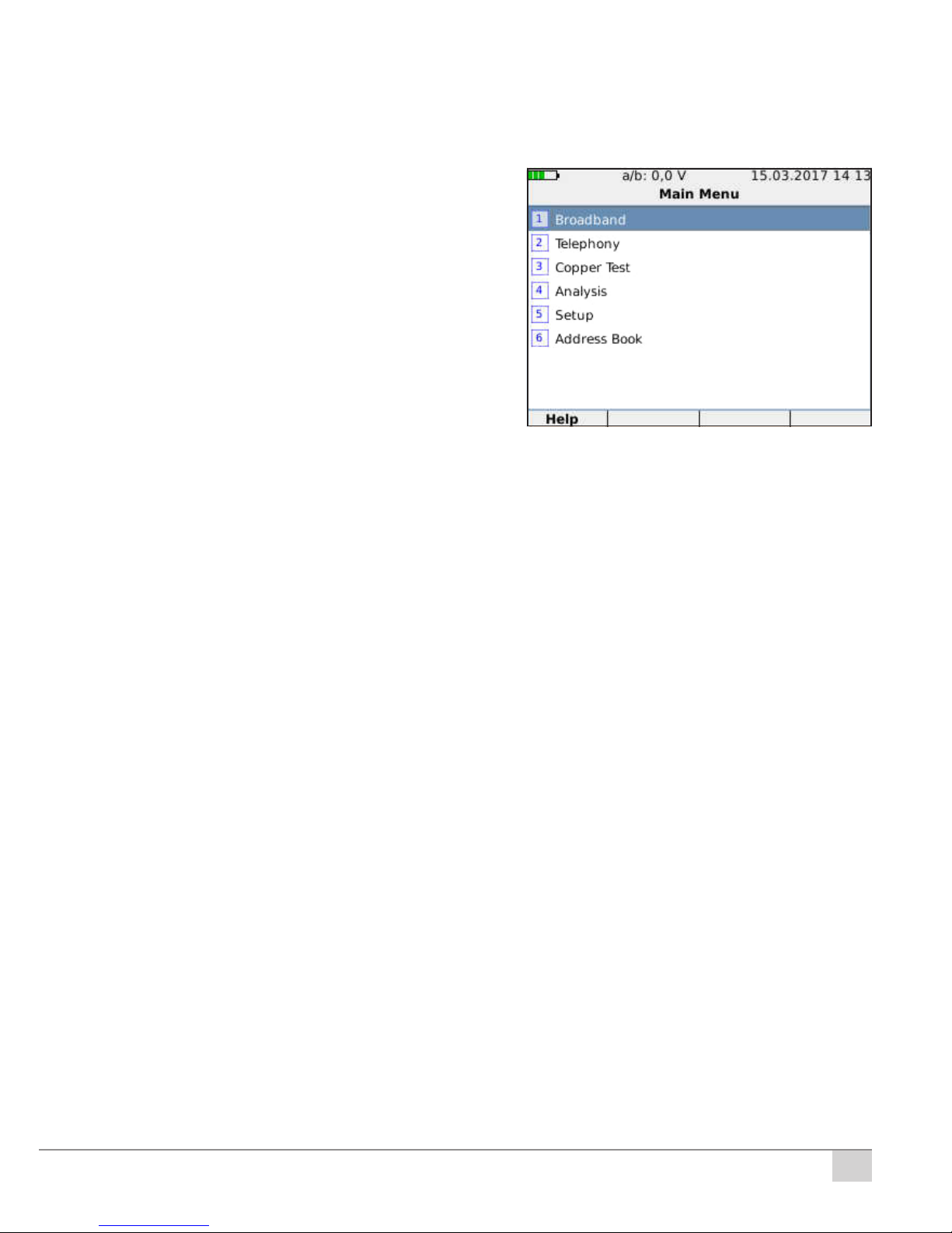
Switch on > Main Menu
After a short boot with subsequent self-test screen appears with the device
information such as rmware version, modem version, installed options and
the hardware ID. Then the main menu appears with the following items:
1. Broadband > Selection of the
interface
2. Telephony (optional)
3. Copper Test (optional)
4. Analysis > Retrieve stored
measurements
5. Setup > Basic Device Settings
6. Address book
Setup
1. Display & Signals:
1.1. Automatic O after the last button is pushed. Possible settings:
Always On / 3 minutes / 5 minutes / 15 minutes / 30 minutes / 60 minutes.
When a test is running, the KE3700 does not shut o even after the time
has elapsed.
1.2. Backlight – Possible settings: Always On / Always O / 3 minutes.
Lets you specify the duration before the screen is dimmed in order to pre-
serve battery life. If 3 minutes is selected, 1.2. Brightness Dimmed ap-
pears as an additional menu item. Possible values are from Level 1 to 7,
whereas 1 is dark and 7 is light. 1.2.3 Brightness: Display brightness,
Level 1 (dark) to 7 (bright).
1.3. Date & Time: 1.3.1 Set Date & Time 1.3.2 Date format DD/MM/YYYY
or MM/DD/YYYY 1.3.3 Time format either
24 hours or 12 hours
1.3.4 Number format x xxx,xx or x,xxx.xx
1.4. Conrm power o: Warning when pressing the ON / OFF button to pre-
vents accidental switching o, On or O
1.5. Storage: Switch between Micro SD card and a USB storage as your
storage location.
1.6. Display Measurements: 1.6.1 Show Min/Max Value (Coppertest >
Line Multimeter) 1.6.2 Show Coppertest length (Coppertest > Line
Multimeter)
1.7. Turn warning signals on or o (e.g. Keypad / Sync / Sync Loss / CRC /
FEC / Low battery)
© Kurth Electronic GmbH, All Rights Reserved
8
1.8. Alarm settings: 1.8.1 A/B Treshold Activation On / O and setting a
threshold value to display the voltage at the upper edge of the display.
2. Language: Setting the menu language
3. Software Updates: Checks if an update is available and allows its in-
stallation (greyed o if there is no update available). See the detailed
rmware update instructions KE-Manager-Firmware-Update.pdf
4. Management Port: Choose between Auto / Static. When Static is selec-
ted, it is possible to dene a xed IP address.
5. Reset Management IF: Reset and restart the Management Interface.
6. System information: Information about the built-in module versions
(hardware and software) and licences.
7. Licence information: Displays open source software used in the device
and the corresponding license terms.
8. Start VNC: Launches virtual network computing (VNC) that displays the
screen contents of the xDSL tester on a local computer (installed using
KE-Manager).
9. Modem Debug: Creates an additional modem log le, On or O
10. Batteriy status: 10.1 Set battery capacity and selection of
10.2 Capacity values of 4000 mAh to 8000 mAh
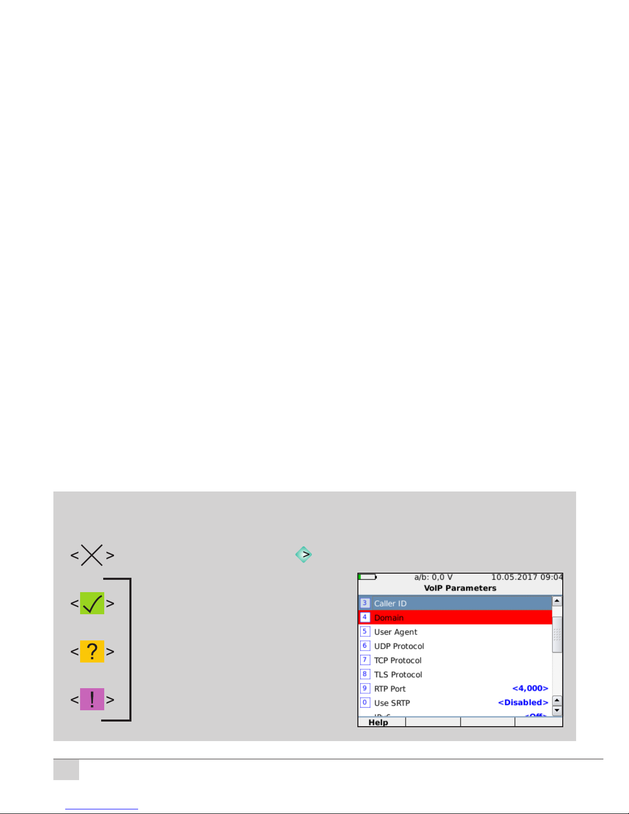
General Operation Help
deactivated, activate with key
activated, all inputs in order
> Testing possible
activated, add inputs
> Testing possible
activated, correct inputs
> Testing impossible
Red bar: Input /
verication required!
© Kurth Electronic GmbH, All Rights Reserved
9
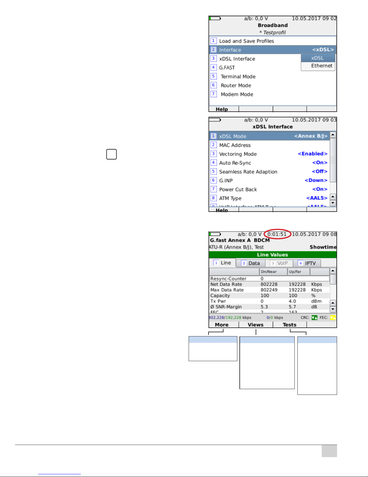
1. Interface
Possible settings: <xDSL> and <Ethernet>
)
When the G.fast modem is installed, menu item
4 G.FAST (On / O) appears for activation.
The menu view changes depending on the
selection.
2. xDSL Interface
Possible settings e.g. <Annex A/M>/ <Annex B/J>.
With Annex J selected, a second synchroniza-
tion approach is needed because the lter from
Annex B to Annex J has to be switched over.
3. Terminal Mode (xDSL) with automatic
DSL Services detection
Synchronization with 1/ Start
Display Line Values
Net Data Rate: Current Up/Downstream
Max Data Rate: Max. Up/Downstream
Capacity: Display in %
Tx Pwr: Transmission power in dBm
Ø SNR Margin: Dierence between line SNR
and required SNR in dB
FEC: Forward Error Correction
CRC: Checksum error
HEC: ATM Header Error Check
Bitswap:Redirected data of a disturbed
communication channel to other channels
Ø Line Atten.: Attenuation in dB
INP: Impulse Noise Protection
Interleave: Delay in ms or 0 for Fast-Path
Line Loss: Loss of synchronized connections
LOF: ATM receiving station has lost
the frame description
LOM: Loss of Margin
SES: Severely Errored Second:
A second with bit error rate
UAS: Number of seconds during which no
transfer was possible
ES: Errored Second: One second of
measurement time during which one
or more bit errors are present
Resync History: During synchonization
Duration of synchronized connection
Help
Reset errors
Save measurement
Zoom
Line Values
PPP Status / IP Status
PPP Log / IP Log
Bands
Vectoring
SNR
BAT
Hlog
QLN
Summary
Web browser
Ping
Traceroute
Http Download
FTP Download
FTP Upload
VoIP Log
VoIP Statistics
VoIP Dial
© Kurth Electronic GmbH, All Rights Reserved
10
Function keys and options
F1 More (Select with SEL)
Help (reserved for help functions)
Reset errors (shown errors will be set to zero)
Save measurement or directly during the measurement by pressing the
SEL key. It opens up a window where the le name can be entered as a
name / number. After conrming with SEL, the measurement is stored on the
internal memory and can be edited using the supplied KE Manager software.
Zoom for graphs (only with SNR / BAT / Hlog / QLN)
F2 Views
(Line values, Bands, Vectoring ...)
Line values (see Page 9)
PPP status / IP protocol
Bands (Displays individual bands for
SNR Margin, Line Attenuation, Signal
attenuation and TX Power)
Vectoring (Vectoring status, G.INP and
possible errors)
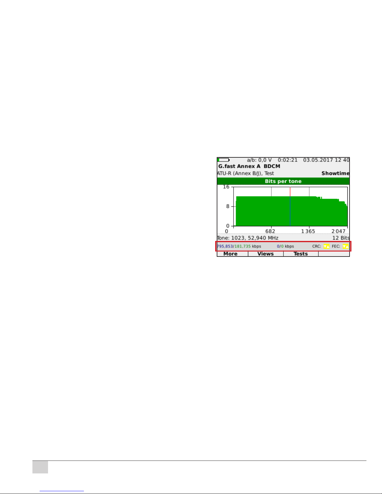
SNR / BAT / Hlog / QLN: Graphs for Bits
per tone, SNR per tone, Hlog and QLN
can be retrieved here (Downstream
blue, Upstream green)
F3 Test
Data tests, VoIP and IPTV tests, web browser
4. Router mode
Connection of the KE3550 to the xDSL port and to the PC. Replaces the
modem and the router.
5. Modem mode
Connection of the KE3550 to the xDSL port and to the PC. Replaces the
modem.
Terminal mode (Ethernet)
Connection to the Ethernet interface of a modem / router or a hub / switch.
Settings for Ping, Traceroute, HTTP Download, FTP Download and FTP
Upload.
Status bar with Data Rate and CRC/FEC
Viewing Bits per tone
Table des matières
Autres manuels Kurth Équipement de test


Manuels Équipement de test populaires d'autres marques

SMART
SMART KANAAD SBT XTREME 3G Series Manuel utilisateur

Agilent Technologies
Agilent Technologies BERT Serial Manuel utilisateur

Agilent Technologies
Agilent Technologies N3280A Manuel utilisateur

Vernier
Vernier Go Direct Voltage Manuel utilisateur

Lifeloc
Lifeloc R.A.D.A.R. Manuel utilisateur

Fluke
Fluke T5-600 Instructions d'utilisation et d'installation


