Kurt MaxLock PF420C Mode d’emploi

PF420C
PF420D
PF420S
Operating Instruction Manual
ENGLISH

2
TABLE OF CONTENTS
Introduction ............................................................................................................ 3
Operating Instructions........................................................................................... 3
Installation & Mounting Guide ..........................................................................4-5
PF420 Parts List .................................................................................................... 6
PF420 Mechanical Drawing ................................................................................ 7
Standard Jaw Options .......................................................................................... 8
Centerline Adjustment & Lash Removal ............................................................ 9
Jaw Removal ........................................................................................................ 10
Machining the Carvable Jaws ........................................................................... 11
Maintenance Schedule ....................................................................................... 12
Maintenance Log/Notes ..................................................................................... 13
Iron Clad Warranty................................................................................................ 14
Thank You! ............................................................................................................. 15
VISE DATA
Use this to ll out information about your vise for quick reference.
Purchase Date: _________ -________ -_________
Purchase Order: ______________________________
Purchased From: ______________________________
Delivery Date: ______________________________
Serial No.: ______________________________
NOTE: MAKE SURE TO REGISTER YOUR WARRANTY
ONLINE AT KURTWORKHOLDING.COM
TABLE OF CONTENTS

3
INTRODUCTION
Thank you for purchasing a Kurt Precision Force vise. The PF Series of
vises are top of the line workholding options for today’s rapidly growing
5-Axis market. Backed by a lifetime warranty against workmanship and
material defects, these vises will perform at the highest levels of precision
and reliability for years to come, when used and maintained properly.
Kurt Anglock maintains it’s time tested design, which gives you the part
pull down that you need when machining high end parts. Other features
Include:
INTRODUCTION
PF Vise Clamp Force
10 ft. lbs. 720 force lbs.
20 ft. lbs. 1,520 force lbs
30 ft. lbs. 2,250 force lbs
40 ft. lbs. 3,050 force lbs
45 ft. lbs. 3,375 force lbs
• Gibbed jaws for maximum clamping
repeatability
• Multiple interchangeable jaw options
‐ Carvable (PF420C)
‐ Dovetail (PF420D)
‐ Serrated (PF420S)
• Easily adjustable center line
• Fast and effortless lash removal system
• Double ended screw for exible vise
operation
OPERATING INSTRUCTIONS
For proper vise operation insert the handle onto the hex of the vise. This
handle, combined with the correct amount of torque will provide you with
all the clamping force you will need to machine your parts. DO NOT use
any other type of pressure to open or close your vise.
The uses of handle extensions, air impact wrenches, breaker bars, or
hammer strikes are not recommended and will void the warranty if used.
This will also cause damage to the central holding block and screw
threads. If you need more clamping force you may require a larger vise.
To properly clamp a part in your Kurt vise you should place the part in
the center of the jaws. Clamping only on one side can result in loss of
accuracy. If one-sided clamping is necessary you MUST use a dummy part
on the other side.

4
INSTALLATION & MOUNTING
All of the vises in the PF Series can be mounted with 1/2 inch SHCS using
the counter-bored through holes in the center of the rails of the vise.
Additional hole locations are shown below.
INSTALLATION & MOUNTING GUIDE
;
PP
;
PP
;'5,//('&%25('
)256+&6
0038//678'
0;7+5($'6;
;.85767$1'$5'
38//678'+2/(6

5
JAW ASSEMBLY
When you receive your new PF Series vise, you will notice that the jaws do
not come attached. To install the vise jaws, follow the steps given below.
1. Place both movable jaws on the rails of the vise, and slide the movable
jaws over the beaks of the nuts.
2. Set the rear covers into their slots in the back of the movable jaws,
then use the button head screws to anchor the rear covers to the
movable jaws.
3. Finish Securing the movable jaws by installing the spring plungers into
the rear covers. Tighten the spring plungers until they are snug, then
loosen them by 1/8 to 1/4 turn.
JAW ASSEMBLY GUIDE
JAW TIGHTENING
SPRING PLUNGER
JAW TIGHTENING
SPRING PLUNGER
MOVABLE JAW
REAR COVER
MOVABLE
JAWS

6PF420 PARTS LIST
PF420 PARTS LIST
ITEM# PART # DESCRIPTION QT Y.
1 PF420-1 Body 1
2 PF420-2* Movable Jaw 2
3 PF420-3R Nut 9/16-18 Right Hand Thread 1
4 PF420-3L Nut 9/16-18 Left Hand Thread 1
5 PF250-5 Screw 1
6 PF420-53 Rear Cover 2
7 PF420-102 Model/Serial Number Tag 1
8 PF420-169 Compression Spring 4
9 DLU4-96 O-Ring #16 2
10 PF250-195 Heavy Duty Square Nut 4
11 PF250-196 Set Screw w/Nyloc Modied 2
12 PF250-212 Central Holding Block 1
15 PF250-272 Thrust Washer Collar 1
17 PF250-311 Straight Wire Spring 2
18 PF250-364L Locking Pin Left Hand 1
19 PF250-364R Locking Pin Right Hand 1
20 PF420-366 Spring Plunger 4
21 3600V-191 Protective Cap 2
22 00-119 SHCS 8-32 X 0.562 LG 4
23 01-1853 Half Dog Set Screw 2
24 03-0021 SBHCS 10-32 X 0.375 LG 4
25 04-0028 Dowel Pin 2
26 07-0230 U-Type Drive Screw 2
27 PF420-16 Pad Guide 4
28 PF420-367 Pull Stud for Lifting Vise 2
29 PF420-10-SA P420-10-SA Handle Assembly 1
*Note: PF420C Carvable Jaw - PF420-2C
PF420D Dovetail Jaw - PF420-2D
PF420S Serrated Jaw - PF420-2S
7
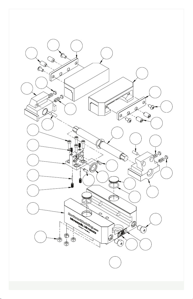
20
24 6
2
27
8
25
5
25 8
4
15
19
18
12
22
23
17
11
21
9
1
10
27
24
20
3
28
7
2
26
HANDLE ASSY
NOT SHOWN
29
6
PF420 MECHANICAL DRAWING
PF420 MECHANICAL DRAWING

8
A
B
DETAIL A
DETAIL B
PF Series Carvable Jaws
Part Number: PF420-2C
PF Series Dovetail Jaws
Part Number: PF420-2D
PF Series Serrated Jaws
Part Number: PF420-2S
STANDARD JAW OPTIONS
STANDARD JAW OPTIONS

9
CENTERLINE ADJUSTMENT & LASH REMOVAL
CENTERLINE ADJUSTMENT
The PF Series of vises are designed for quick and easy adjustment of the
vise centerline.
1. Loosen the four centerline adjustment bolts using a 9/64 hex wrench
2. Adjust the centerline by sliding the nut and screw assembly within the
body of the vise. A mallet may be required to gently tap the ends of
the screw in the direction of the desired adjustment.
3. When the centerline is in the desired position, re-tighten the four
centerline adjustment bolts.
LASH REMOVAL
Along with an easily adjustable centerline, the PF vises also have an
extremely simple to use lash removal system.
1. Loosen the two lash release bolts on the top surface of the central
holding block, using a 5/64 hex wrench.
2. Tap the top of the central holding block with your nger.
3. Re-tighten the lash release bolts.
CENTERLINE ADJUSTMENT
BOLTS (4X)
LASH RELEASE
BOLTS (2X)

10
JAW REMOVAL
The Jaws on the PF 420 are easily removed. The following steps will help
you remove them for replacement or maintenance purposes.
1. Loosen the spring plungers with a at head screwdriver, to remove any
spring forces that may be pushing against the rear cover plate.
2. Loosen and remove the two button head screws that attach the rear
cover plate to the movable jaw, using a 1/8 hex wrench.
3. Slide the free jaw forward on the bed of the vise until it clears the beak
of the nut. Then lift the freed jaw off of the vise.
4. Repeat the above process for the second jaw.
JAW REMOVAL
BUTTON HEAD SCREWS
ATTACH REAR COVER
TO JAW
SPRING PLUNGERS
TIGHTEN JAW TO NUT
Ce manuel convient aux modèles suivants
2
Table des matières
Autres manuels Kurt Outils électriques


