KNX PY Mode d’emploi

Installation and Adjustment
EN
Elsner Elektronik GmbH Control and AutomationTechnology
Herdweg 7
D – 75391 Gechingen Phone +49 (0) 70 56 / 93 97-0 info@elsner-elektronik.de
Germany Fax +49 (0) 70 56 / 93 97-20 www.elsner-elektronik.de
KNX PY
Global Irradiance Sensor
Item number 70157

1 Content
Elsner Elektronik GmbH • Herdweg 7 • D-75391 Gechingen • Germany
Pyranometer KNX PY • from software version 1.00, ETS programme version 1.11
Status: 21.08.2013 • Errors excepted. Subject to technical changes.
1. Description ........................................................................................... 3
1.1. Scope of delivery ...................................................................................................... 3
1.2. Technical specifications ........................................................................................... 3
2. Installation and commissioning ........................................................... 4
2.1. Installation notes ...................................................................................................... 4
2.2. Location ..................................................................................................................... 5
2.3. Mounting the sensor ................................................................................................ 5
2.3.1. Attaching the mount ..................................................................................... 5
2.3.2. View of rear side and drill hole plan ........................................................... 7
2.3.3. Preparing the sensor .................................................................................... 8
2.3.4. PCB layout ..................................................................................................... 8
2.3.5. Mounting the sensor .................................................................................... 9
2.4. Notes on mounting and commissioning ................................................................ 9
3. Addressing of the device at the bus .................................................... 9
4. Maintenance ....................................................................................... 10
5. Transmission Protocol ....................................................................... 11
5.1. List of all communication objects ......................................................................... 11
6. Setting of parameters ........................................................................ 13
6.1. General settings ..................................................................................................... 13
6.2. Threshold values .................................................................................................... 14
6.2.1. Threshold value 1 / 2 / 3 / 4 ........................................................................ 14
6.3. Logic ........................................................................................................................ 15
6.3.1. AND Logic 1 / 2 ............................................................................................ 16
6.3.2. Linkage inputs of AND Logic ..................................................................... 17
6.3.3. OR Logic 1 / 2 .............................................................................................. 17
6.3.4. Linkage inputs of OR Logic ........................................................................ 18

2 Clarification of signs
This manual is amended periodically and will be brought into line with new software
releases. The change status (software version and date) can be found in the contents footer.
If you have a device with a later software version, please check
www.elsner-elektronik.de in the menu area "Service" to find out whether a more up-to-
date version of the manual is available.
Clarification of signs used in this manual
Installation, inspection, commissioning and troubleshooting of the device
must only be carried out by a competent electrician.
Safety advice.
Safety advice for working on electrical connections, components,
etc.
DANGER! ... indicates an immediately hazardous situation which will lead to
death or severe injuries if it is not avoided.
WARNING! ... indicates a potentially hazardous situation which may lead to
death or severe injuries if it is not avoided.
CAUTION! ... indicates a potentially hazardous situation which may lead to
trivial or minor injuries if it is not avoided.
ATTENTION! ... indicates a situation which may lead to damage to property if it is
not avoided.
ETS In the ETS tables, the parameter default settings are marked by
underlining.

3 Description
Pyranometer KNX PY • Status: 21.08.2013 • Technical changes reserved. Errors reserved.
1. Description
The Pyranometer KNX PY measures global irradiance, which is perceived as heat.
The measured current irradiance (watts per squaremetre) allows for drawing conclu-
sions on the energy input to an area during a defined period of time (kilowatt hours per
squaremetre). Both values can be read out by the KNX PY. Four switching outputs
with adjustable threshold values as well as additional AND and OR logic gates are
available.The sensor system, the evaluation electronics and the electronics of the bus
connection are mounted in a compact housing.
Functions:
•Measurement of global irradiance: The current irradiance is measured
(W/m²). The energy input to an area during a defined period of time can be read
out (kWh/m²)
•4 switching outputs with adjustable threshold values (Threshold values can
be set by parameter or via communication objects)
•2 AND and 2 OR logic gates with each 4 inputs. Every switching incident as
well as 8 logic inputs (in the form of communication objects) may be used as
inputs for the logic gates. The output of each gate may optionally be configured
as 1 bit or 2 x 8 bits
Configuration is made using the KNX software ETS. The programme file (format VD),
the data sheet and the manual can be downloaded from the Elsner Elektronik
homepage on www.elsner-elektronik.de in the “Service” menu.
1.1. Scope of delivery
• Pyranometer with combined wall/pole mounting
• 2 mounting brackets for pole mounting (Ø 40-60 mm)
1.2. Technical specifications
Housing Plastic material
Colour White / Transparent
Mounting On-wall
Protection category IP 44
Dimensions approx. 96 × 77 × 118 (W × H × D, mm)
Weight approx. 145 g
Ambient temperature Operation -25…+85°C, storage -30…+85°C
Operating voltage KNX bus voltage
Bus current max. 7 mA,
max. 10 mA when programming LED is active
Data output KNX +/- bus terminal plug
BCU type Own micro controller
PEI type 0
Group addresses max. 200
4 Installation and commissioning
Pyranometer KNX PY • Status: 21.08.2013 • Technical changes reserved. Errors reserved.
The product conforms with the provisions of EC guidelines
• EMC Directive 2004/108/EC
• Low Voltage Directive 2006/95/EC
The following standards and/or technical specifications have been applied:
• EN 50491-5-1: 2010
• EN 50491-5-2: 2011
2. Installation and commissioning
2.1. Installation notes
Installation, testing, operational start-up and troubleshooting should
only be performed by an electrician.
CAUTION!
Live voltage!
There are unprotected live components inside the device.
• National legal regulations are to be followed.
• Ensure that all lines to be assembled are free of voltage and take
precautions against accidental switching on.
• Do not use the device if it is damaged.
• Take the device or system out of service and secure it against
unintentional use, if it can be assumed, that risk-free operation is no
longer guaranteed.
The device is only to be used for its intended purpose. Any improper modification or
failure to follow the operating instructions voids any and all warranty and guarantee
claims.
After unpacking the device, check it immediately for possible mechanical damage. If it
has been damaged in transport, inform the supplier immediately.
The device may only be used as a fixed-site installation; that means only when assem-
bled and after conclusion of all installation and operational start-up tasks and only in
the surroundings designated for it.
Allocations max. 200
Communication objects 52
Measurement range 0…2500 W/m²
0…2196 kWh/m²
Measurement range 5 W/m²
0.1 kWh/m²
Accuracy ± 15% of the measured value
at above 150 W/m²

5 Installation and commissioning
Pyranometer KNX PY • Status: 21.08.2013 • Technical changes reserved. Errors reserved.
Elsner Elektronik is not liable for any changes in norms and standards which may occur
after publication of these operating instructions.
2.2. Location
Select an assembly location at the building where sun may be collected by the sensors
unobstructedly. The sensor may not be shaded by the building or for example by trees.
2.3. Mounting the sensor
2.3.1. Attaching the mount
The sensor comes with a combination wall/pole mount. The mount comes adhered by
adhesive strips to the rear side of the housing. Fasten the mount vertically onto the wall
or pole.
Fig. 1
The sensor must be mounted onto a vertical
wall (or pole).
Wall
or
pole
Fig. 2
The sensor must be mounted horizontally in
the lateral direction.
horizontal
Fig. 3
When wall mounting: flat side on wall, crescent-
shaped collar upward.
Collar

6 Installation and commissioning
Pyranometer KNX PY • Status: 21.08.2013 • Technical changes reserved. Errors reserved.
Fig. 4
When pole mounting: curved side on pole, collar
downward.
Collar
Fig. 5
Different mounting arms are available from El-
sner Elektronik as additional, optional accesso-
ries for flexible installation of the weather station
on a wall, pole or beam.
Example of the use of a mounting arm: Due to
flexible ball joints, the sensor can be brought
into ideal position.
Fig. 6
Example use of the hinge arm mounting:
With the hinge arm mounting, the weather sta-
tion projects from beneath the roof overhang.
Sun, wind and precipitation can act upon the
sensors without hindrance.
Fig. 7
Example use of the hinge arm mounting:
Fitting to a pole with worm drive hose clips

7 Installation and commissioning
Pyranometer KNX PY • Status: 21.08.2013 • Technical changes reserved. Errors reserved.
2.3.2. View of rear side and drill hole plan
Langloch 7,5 x 5 mm
Fig. 8 a+b
Drill hole plan
Dimensions of rear side of
housing with bracket. Sub-
ject to change for technical
enhancement.
8 Installation and commissioning
Pyranometer KNX PY • Status: 21.08.2013 • Technical changes reserved. Errors reserved.
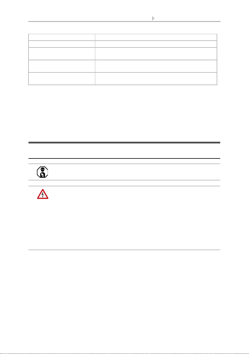
2.3.3. Preparing the sensor
The sensor cover snaps in on the left and right along the bottom edge (see Fig.).
Remove the cover.
Push the connection cable through the rubber seal on the bottom of the device and
connect voltage and data cable to the provided clamps.
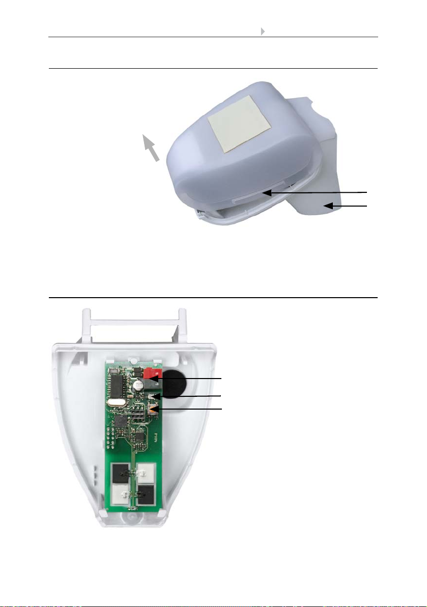
2.3.4. PCB layout
Fig. 9
1 Cover snaps
2 Bottom part of housing
1
2
Unsnap cover
and remove upwards
Fig. 10
1KNXclamp+/-
2 Programming LED
3 Programming pushbutton for
the teach-in of the device
1
2
3

9 Addressing of the device at the bus
Pyranometer KNX PY • Status: 21.08.2013 • Technical changes reserved. Errors reserved.
2.3.5. Mounting the sensor
Close the housing by putting the cover back over the bottom part. The cover must snap
in on the left and right with a definite “click”.
To remove it, the sensor can be simply pulled upwards out of the mount, against the
resistance of the fastening.
2.4. Notes on mounting and commissioning
Do not open the device if water (rain) might ingress: even some drops might damage
the electronic system.
After the bus voltage has been applied, the device will enter an initialisation phase last-
ing a few seconds. During this phase no information can be received via the bus.
3. Addressing of the device at the bus
The device is supplied with the bus address 15.15.250. You can program another ad-
dress into the ETS by overwriting the 15.15.250 address or by teaching via the pro-
gramming key on the circuit board inside the housing.
Fig. 11
Make sure the cover and bottom part are
properly snapped together! This picture is
looking at the closed sensor from under-
neath.
Fastening
Fig. 12
Push the housing from above into the fas-
tened mount. The bumps on the mount must
snap into the rails in the housing.
Ce manuel convient aux modèles suivants
1
Table des matières
Autres manuels KNX Instrument de mesure


Manuels Instrument de mesure populaires d'autres marques


Endress+Hauser
Endress+Hauser Proline Promag 50 Caractéristiques techniques

Siemens
Siemens SITRANS F Coriolis FCT030 Manuel de la liste des pièces

KLINGER
KLINGER CMF V Series Manuel utilisateur

EXFO
EXFO FTB-2 Manuel d'exploitation et d'entretien

Keysight
Keysight M8290A Manuel utilisateur

ADTEK
ADTEK MW-5 Manuel utilisateur