
KME DAP 26 Manuel utilisateur

User Manual
DAP 26
Digital Audio Processor
KME-Control
Remote Software Mainframe

DAP 26 HW Version 1.2 r0026
DAP 26 MC Version 1.1 r0052
KME-Control Version 1.00 Build 0073
DAP 26 Plug Version 1.00 Build 0149
Manual Rev. Version 1.00 EN

Functional units
The DAP 26 offers a lot of functional units for general audio processing using a
powerful DSP mainframe such as 9 filter banks with each 5 configurable filters of 9
different types, 6 crossover units with two combinable filters out of 3 types, 3 master
delays (up to 2000 ms / 685 meters), 6 channel delays (up to 500 ms / 170 meters)
and 6 dynamic processors (compressor / limiter / noise gate).
All this functional units can be programmed either directly on the hardware unit or by
using the real-time control software ‚KMEControl’..
Switches and Knobs
Front side
IN A IN B
LIMIT LIMIT LIMIT
0
+
dB
-60
CLIP
0
+
dB
-60
0
+
dB
-60
0
+
dB
-60
MU TE
dB-6 +6
MUT E
dB-6 +6
MU TE
dB-6 +6
MUTE MU TE MUTE
dB-6 +6 dB-6 +6 dB-6 +6
K.M.E. DAP26 V0.1
Preset Configur ation
Choose an option!
Input level meters
Two 10-digit digital level meters help to set the correct input level on the analog audio
inputs or to monitor the digital audio input level.
The graphic below shows different peak input levels on your unit:
abcd
a) too less input level
b) input level OK
c) maximum input level
d) too much input level – clipping may occur
The analog input circuit contains a limiter unit for preventing the A/D- converters from
clipping. Nevertheless the analog input level must not exceed the red LED of the
input level meter to prevent reproduction of a distorted signal. Set the source level
that only the yellow LEDs light up in peaks.

Display
K.M.E. DAP26 V0.1
Preset Configuration
Choose an option!
A 4x20 back-lighted LCD display shows the navigation menu. You can set all
software parameters on the unit itself. Arrows in the lower right corner show the
directions to navigate to submenus. (see appendix ‘navigation structure’). Use the
navigation pad to move between the menus. Press the ‘OK’ button to select a
parameter if you are asked by the unit.
Navigation Pad
The navigation pad is to be used for accessing and changing parameters on the
display of the hardware unit. Press the OK button if you are asked by the software.
See also the appendix ‘menu structure’!
Level meter 1-6
Level correction 1-6
Mute switch 1-6
LIMIT
0
+
dB
-60
MUTE
dB-6 +6
MUTE
dB-6 +6
The level correction pot adjusts the output level of the corresponding channel by +/- 6
dB. This is done on digital signal level and independent from the gain correction in
the software plug-in.
Pressing the mute switch mutes the corresponding output channel. The level meter
still displays the output level to avoid unintentional triggering of the switches.

There is a 10-digit LED bar-graph for each output channel which displays the
following information:
abc
a) there is an output signal on channel X (if the mute switch is not activated)
b) the signal on output X exceeds the maximum output level (if the mute switch is
not activated)
c) there is an output signal on channel X, the dynamic processor (Compressor/
Limiter) is activated and works
Mains switch
Use this switch for powering up the hardware unit. We included a power-up delay
which prevents clicks or plops in the speakers efficiently, nevertheless we
recommend switching on your power amplifiers after the DAP.
The backlighting of the display shows that the DAP is switched on and the mains
power is within the useable range. If the display does not light check your mains
voltage and / or the mains fuse which is located in the mains connector.

Connectors
Rear side
DIGITAL OUTPUT INPUT
INPUT 6 4 2 B
INPUT
+6dB
531 AOUTPU T
DAP 26
KLINGENTHALER
MUSIKELEKTRONIK
GmbH
MA DE IN G ERMA NY
FUSE
1 AT
85- 264V~AC ;
50-60Hz
CAN 1 / RS 232
CAN 2
CAUTION!
PULL
PLUG
BEFORE
OPENING!
There are all connectors located on the rear side of the unit.
Analog inputs / level select switch
INPUT
B
INPUT
+6dB
A
The audio inputs of the DAP 26 are electronically balanced. Unless it is necessary we
do not recommend unbalanced audio connections. The inputs have to be operated
with an nominal audio level of either 775 mV (0 dB) or 1.55V (+6 dB) which you can
select using the switch beside the connector “b” corresponding to the signal level
your source units work with.
1
2
3
12
3
XLR-to- XLR balanced audio connection
12
3
Jack-to-XLR balanced audio connection
Use one of this cables for connecting the analog audio inputs of the DAP 26 to your
mixer / stagebox or to another signal source.
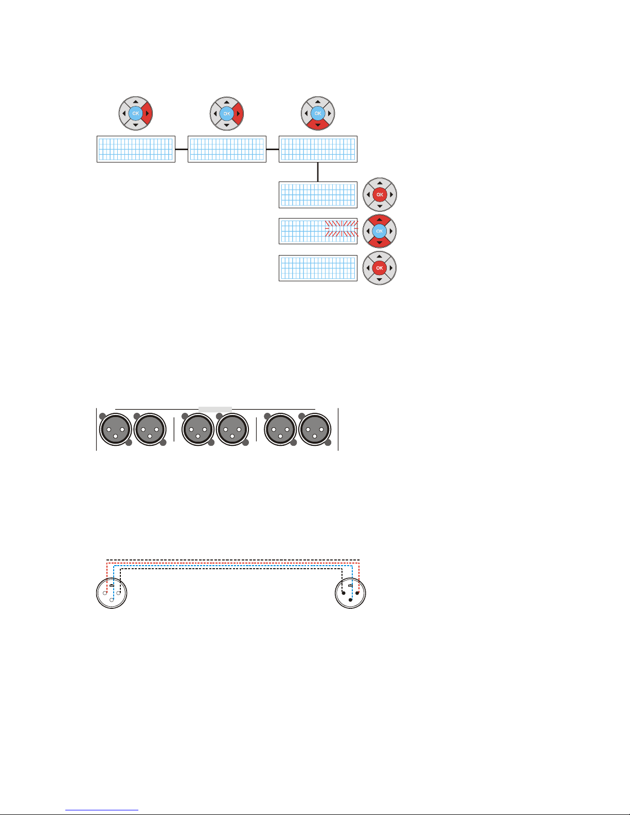
Switching inputs to ‚analog’ (factory preset)
K.M.E. DAP26
Presetinfo
Choose an option!‹ ›
ˆ
K.M.E. DAP26
Devicesettin
g
Choose an o
p
tion!‹ ›
ˆ
Devicesettin
g
s
In-select: Di
g
ital
OK: Chan
g
e Value ˆ>
K.M.E. DAP26
Preset Configuration
Choose an option! >
ˆ
Devicesettin
g
s
In-select: Analo
g
OK: Chan
g
e Value ˆ>
Devicesettin
g
s
In-select: Analo
g
OK: Chan
g
e Value ˆ>
ˆˆˆ
Follow this navigation scheme to activate the analog audio inputs (factory preset)
?after using the digital audio input sometimes?. This is one of the few settings that
can only be done on the hardware unit itself.
Analog outputs 1-6
OUTPUT
642531
The analog audio outputs 1-6 are electronically balanced, male XLR sockets. We do
not recommend connecting unbalanced destination devices to the DAP 26. The
nominal output level is reached if the yellow LED in the level meter lights up.
1
2
3
12
3
XLR-to- XLR balanced audio connection
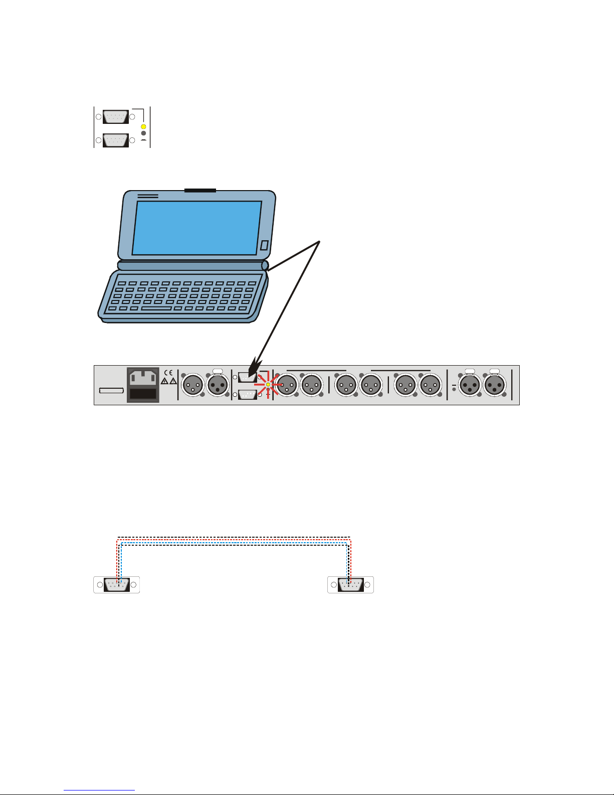
Computer connection,
selector RS 232 – CAN
CAN 1 / RS 232
CAN 2
• programming the unit (on PC using RS 232)
DIGITAL OUTPUT INPUT
INPUT 6 4 2 B
INPUT
+6dB
531 AOUTPUT
DAP26
KLINGENTHALER
MUSIKELEKTRONIK
GmbH
MADE IN G ERMAN Y
FUSE
1 AT
85-264V ~AC ;
50-60Hz
CAN 1 / RS 2 32
CAN 2
CAUTION!
PULL
PLUG
BEFORE
OPEN ING!
RS 232
COM 1
X
Connect the DAP 26 to a free COM port of your PC using the supplied RS232 cable.
You must only use the upper connector labelled ‘RS232/CAN’. Make sure that the
yellow LED beside the connector GLOWS BEFORE connecting the unit to your PC! If
the LED does NOT glow, operate the switch which is located just below this LED
using a suitable tool.
You can now run the ‘KME-Control’ software and activate the communication (see
software).
15324
7896
15324
7896
9-pole D-sub cable 1:1 as supplied with the DAP 26. The pins shown in this drawing
have to be connected, the other pins may be connected but do not affect the
communication at all.
The maximum length of such a cable MUST NOT EXCEED 5 meters or the
communication may be interfered!

• Remote use (PC with USB- port and K.M.E. CAN- Interface)
DIGITAL OUTPUT INPUT
INPUT 6 4 2 B
INPUT
+6dB
531 AOUTPUT
DAP26
KLINGENTHALER
MUSIKELEKTRONIK
GmbH
MADE IN G ERMAN Y
FUSE
1 AT
85-264V ~AC ;
50-60Hz
CAN 1 / RS 2 32
CAN 2
CAUTION!
PULL
PLUG
BEFORE
OPEN ING!
USB CAN Port
CAN Bus
1...>250 m
AFTER the installation of the KMEControl mainframe software you can connect the
USB port on your computer with the K.M.E. CANport interface using the supplied
USB cable. All necessary device drivers will be loaded automatically when
connecting the interface for the first time. Make sure that the yellow LED does not
light before connecting the CANport interface to your DAP 26 using the supplied or a
modified cable. Connect the supplied CAN terminator plug to the lower socket of your
DAP 26. If there are more DAPs daisy-chained, connect the CAN terminator plug to
the free connector of the last device in your CAN chain!
You can now run KMEControl software and activate the communication (see
software).
15324
7896
15324
7896
CAN Bus Link cable
This cable can be used connecting the DAP 26 to the CAN port interface box. Use
such cable also for linking the CAN bus from unit to unit. Do not forget connecting the
CAN terminator plug to the free connection port of the last unit, otherwise the CAN
transmission could be disturbed.
Note: By using a self-made cable make sure to connect the pins needed for CAN
transmission. They are different than in RS232 mode unless using 9 wire cable!

This cable can be used connecting the DAP 26 to the CAN port interface box, using
your multicore system (i.e. XLR). Use such cable also for linking the CAN bus from
unit to unit. Do not forget connecting the CAN terminator plug to the free connection
port of the last unit, otherwise the CAN transmission could be disturbed.
1
2
3
15324
7896
15324
7896
12
3
Digital Audio Input
Digital Audio Output
DIGITAL
INPUTOUTPUT
The digital input accepts digital audio signals according to AES/EBU with a bit rate of
16 to 24 and a sampling frequency of 32 to 96 kHz using an internal format-/sample
rate converter chip. The digital audio output loops the selected input (analog/digital)
as a 24-bit/96 kHz AES/EBU signal for cascading additional units or recording the
signal to a studio digital recorder. All digital connections are transformer- balanced for
maximum protection against ground loops.
1
2
3
12
3
Digital Audio Connection Cable (AES/ EBU) w. 110 Ohms
We do not recommend using “normal microphone cable” for AES/EBU connections
also when it ‘seems’ to work. Only specified 110 Ohms digital audio cable will give a
proper connection without data loss and digital drop-outs.
Table des matières


