Keysight Technologies U3024AH10 Manuel

User's and
Service Guide
Keysight Technologies
U3024AH10
Multiport Test Set
Use this manual with the following document: PNA
Series Network Analyzer On-Line Help System
Notice: This document contains references to
Agilent Technologies. Agilent's former Test and
Measurement business has become Keysight
Technologies. For more information, go to
www.keysight.com.

Notices
© Keysight Technologies, Inc. 2011,
2014, 2017, 2020
No part of this manual may be
reproduced in any form or by any
means (including electronic storage
and retrieval or translation into a
foreign language) without prior
agreement and written consent
from Keysight Technologies, Inc. as
governed by United States and
international copyright laws.
Trademark Acknowledgments
Manual Part Number
U3024-90001
Edition
Edition 4, January 2020
Supersedes July 2017
Printed in USA
Published by:
Keysight Technologies
1400 Fountaingrove Parkway
Santa Rosa, CA 95403
Warranty
THE MATERIAL CONTAINED IN
THIS DOCUMENT IS PROVIDED “AS
IS,” AND IS SUBJECT TO BEING
CHANGED, WITHOUT NOTICE, IN
FUTURE EDITIONS. FURTHER, TO
THE MAXIMUM EXTENT PERMITTED
BY APPLICABLE LAW, KEYSIGHT
DISCLAIMS ALL WARRANTIES,
EITHER EXPRESS OR IMPLIED WITH
REGARD TO THIS MANUAL AND
ANY INFORMATION CONTAINED
HEREIN, INCLUDING BUT NOT
LIMITED TO THE IMPLIED
WARRANTIES OF
MERCHANTABILITY AND FITNESS
FOR A PARTICULAR PURPOSE.
KEYSIGHT SHALL NOT BE LIABLE
FOR ERRORS OR FOR INCIDENTAL
OR CONSEQUENTIAL DAMAGES IN
CONNECTION WITH THE
FURNISHING, USE, OR
PERFORMANCE OF THIS
DOCUMENT OR ANY INFORMATION
CONTAINED HEREIN. SHOULD
KEYSIGHT AND THE USER HAVE A
SEPARATE WRITTEN AGREEMENT
WITH WARRANTY TERMS
COVERING THE MATERIAL IN THIS
DOCUMENT THAT CONFLICT WITH
THESE TERMS, THE WARRANTY
TERMS IN THE SEPARATE
AGREEMENT WILL CONTROL.
Technology Licenses
The hardware and/or software
described in this document are
furnished under a license and may be
used or copied only in accordance
with the terms of such license.
U.S. Government Rights
The Software is “commercial computer
software,” as defined by Federal
Acquisition Regulation
(“FAR”) 2.101. Pursuant to FAR
12.212 and 27.405-3 and
Department of Defense FAR
Supplement (“DFARS”) 227.7202, the
U.S. government acquires
commercial computer software under
the same terms by which the
software is customarily provided to
the public. Accordingly, Keysight
provides the Software to U.S.
government customers under its
standard commercial license, which
is embodied in its End User License
Agreement (EULA), a copy of which
can be found at
http://www.keysight.com/find/sweu
la. The license set forth in the EULA
represents the exclusive authority by
which the U.S. government may use,
modify, distribute, or disclose the
Software. The EULA and the license
set forth therein, does not require or
permit, among other things, that
Keysight: (1) Furnish technical
information related to commercial
computer software or commercial
computer software documentation
that is not customarily provided to
the public; or (2) Relinquish to, or
otherwise provide, the government
rights in excess of these rights
customarily provided to the public to
use, modify, reproduce, release,
perform, display, or disclose
commercial computer software or
commercial computer software
documentation. No additional
government requirements beyond
those set forth in the EULA shall
apply, except to the extent that those
terms, rights, or licenses are explicitly
required from all providers of
commercial computer software
pursuant to the FAR and the DFARS
and are set forth specifically in
writing elsewhere in the EULA.
Keysight shall be under no obligation
to update, revise or otherwise modify
the Software. With respect to any
technical data as defined by FAR
2.101, pursuant to FAR 12.211 and
27.404.2 and DFARS 227.7102, the
U.S. government acquires no
greater than Limited Rights as
defined in FAR 27.401 or DFAR
227.7103-5 (c), as applicable in any
technical data.
Safety Notices
A CAUTION notice denotes a hazard.
It calls attention to an operating
procedure, practice, or the like that,
if not correctly performed or
adhered to, could result in damage
to the product or loss of important
data. Do not proceed beyond a
CAUTION notice until the indicated
conditions are fully understood and
met.
A WARNING notice denotes a hazard.
It calls attention to an operating
procedure, practice, or the like that,
if not correctly performed or
adhered to, could result in personal
injury or death. Do not proceed
beyond a WARNING notice until the
indicated conditions are fully
understood and met.

U3024AH10
Contents-1
Introduction. . . . . . . . . . . . . . . . . . . . . . . . . . . . . . . . . . . . . . . . . . . . . . . . . . . . . . . . . . . . . . . . . . . . . . . . . . . . . . . . 1
Description . . . . . . . . . . . . . . . . . . . . . . . . . . . . . . . . . . . . . . . . . . . . . . . . . . . . . . . . . . . . . . . . . . . . . . . . . . . . . . . . 3
Measurement Application Notes . . . . . . . . . . . . . . . . . . . . . . . . . . . . . . . . . . . . . . . . . . . . . . . . . . . . . . . . . . . . . 3
Low Loss DUT Measurements. . . . . . . . . . . . . . . . . . . . . . . . . . . . . . . . . . . . . . . . . . . . . . . . . . . . . . . . . . . . . . 3
Switch Configuration Command Speed . . . . . . . . . . . . . . . . . . . . . . . . . . . . . . . . . . . . . . . . . . . . . . . . . . . . . . 3
Verifying the Shipment . . . . . . . . . . . . . . . . . . . . . . . . . . . . . . . . . . . . . . . . . . . . . . . . . . . . . . . . . . . . . . . . . . . . . 4
Network Analyzer Requirements. . . . . . . . . . . . . . . . . . . . . . . . . . . . . . . . . . . . . . . . . . . . . . . . . . . . . . . . . . . . . . 4
Definitions . . . . . . . . . . . . . . . . . . . . . . . . . . . . . . . . . . . . . . . . . . . . . . . . . . . . . . . . . . . . . . . . . . . . . . . . . . . . . . . 4
Available Options . . . . . . . . . . . . . . . . . . . . . . . . . . . . . . . . . . . . . . . . . . . . . . . . . . . . . . . . . . . . . . . . . . . . . . . . . . . 5
Test Set Options . . . . . . . . . . . . . . . . . . . . . . . . . . . . . . . . . . . . . . . . . . . . . . . . . . . . . . . . . . . . . . . . . . . . . . . . . . 5
Front Handle and Rack Kits . . . . . . . . . . . . . . . . . . . . . . . . . . . . . . . . . . . . . . . . . . . . . . . . . . . . . . . . . . . . . . . . . 5
Network Analyzer Interface Kit Options . . . . . . . . . . . . . . . . . . . . . . . . . . . . . . . . . . . . . . . . . . . . . . . . . . . . . . . . 5
Specifications . . . . . . . . . . . . . . . . . . . . . . . . . . . . . . . . . . . . . . . . . . . . . . . . . . . . . . . . . . . . . . . . . . . . . . . . . . . . . . 6
Power Requirements . . . . . . . . . . . . . . . . . . . . . . . . . . . . . . . . . . . . . . . . . . . . . . . . . . . . . . . . . . . . . . . . . . . . . . . 6
Environmental Requirements . . . . . . . . . . . . . . . . . . . . . . . . . . . . . . . . . . . . . . . . . . . . . . . . . . . . . . . . . . . . . . . . 7
Environmental Tests . . . . . . . . . . . . . . . . . . . . . . . . . . . . . . . . . . . . . . . . . . . . . . . . . . . . . . . . . . . . . . . . . . . . . 7
Equipment Heating and Cooling. . . . . . . . . . . . . . . . . . . . . . . . . . . . . . . . . . . . . . . . . . . . . . . . . . . . . . . . . . . . 7
Required Conditions for Accuracy Enhanced Measurement . . . . . . . . . . . . . . . . . . . . . . . . . . . . . . . . . . . . . .7
Dimensions and Space Requirements . . . . . . . . . . . . . . . . . . . . . . . . . . . . . . . . . . . . . . . . . . . . . . . . . . . . . . . 7
Frequency Range and Maximum Power Levels . . . . . . . . . . . . . . . . . . . . . . . . . . . . . . . . . . . . . . . . . . . . . . . . . . 8
Reflection Tracking Performance . . . . . . . . . . . . . . . . . . . . . . . . . . . . . . . . . . . . . . . . . . . . . . . . . . . . . . . . . . . . . 9
Front and Rear Panel Features . . . . . . . . . . . . . . . . . . . . . . . . . . . . . . . . . . . . . . . . . . . . . . . . . . . . . . . . . . . . . . . . 10
14-Port System Setup . . . . . . . . . . . . . . . . . . . . . . . . . . . . . . . . . . . . . . . . . . . . . . . . . . . . . . . . . . . . . . . . . . . . . . 15
Attaching the Test Set to the Network Analyzer . . . . . . . . . . . . . . . . . . . . . . . . . . . . . . . . . . . . . . . . . . . . . . . . 15
14-Port System Interface Cable Connections . . . . . . . . . . . . . . . . . . . . . . . . . . . . . . . . . . . . . . . . . . . . . . . . . . 18
24-Port System Setup . . . . . . . . . . . . . . . . . . . . . . . . . . . . . . . . . . . . . . . . . . . . . . . . . . . . . . . . . . . . . . . . . . . . . . 20
Attaching the Test Set to the Network Analyzer . . . . . . . . . . . . . . . . . . . . . . . . . . . . . . . . . . . . . . . . . . . . . . . . 20
Preparing the Two Test Sets . . . . . . . . . . . . . . . . . . . . . . . . . . . . . . . . . . . . . . . . . . . . . . . . . . . . . . . . . . . . . . . . 21
24-Port System Interface Cable Connections . . . . . . . . . . . . . . . . . . . . . . . . . . . . . . . . . . . . . . . . . . . . . . . . . . 24
System Operational Check . . . . . . . . . . . . . . . . . . . . . . . . . . . . . . . . . . . . . . . . . . . . . . . . . . . . . . . . . . . . . . . . . . . 27
Equipment Setup . . . . . . . . . . . . . . . . . . . . . . . . . . . . . . . . . . . . . . . . . . . . . . . . . . . . . . . . . . . . . . . . . . . . . . . . 27
Verify Results . . . . . . . . . . . . . . . . . . . . . . . . . . . . . . . . . . . . . . . . . . . . . . . . . . . . . . . . . . . . . . . . . . . . . . . . . . . 27
Controlling the System with the Network Analyzer . . . . . . . . . . . . . . . . . . . . . . . . . . . . . . . . . . . . . . . . . . . . . . . . 30
Sweep Setup for Multiport and Standalone PNA Modes. . . . . . . . . . . . . . . . . . . . . . . . . . . . . . . . . . . . . . . . . . 30
PNA-X Multiport Mode . . . . . . . . . . . . . . . . . . . . . . . . . . . . . . . . . . . . . . . . . . . . . . . . . . . . . . . . . . . . . . . . . . . . 31
Multiport Mode Operation . . . . . . . . . . . . . . . . . . . . . . . . . . . . . . . . . . . . . . . . . . . . . . . . . . . . . . . . . . . . . . . 31
External Test Set Control Operation . . . . . . . . . . . . . . . . . . . . . . . . . . . . . . . . . . . . . . . . . . . . . . . . . . . . . . . . 32
Selecting S-Parameter Measurement . . . . . . . . . . . . . . . . . . . . . . . . . . . . . . . . . . . . . . . . . . . . . . . . . . . . . . 33
Selecting New S-Parameter Measurement . . . . . . . . . . . . . . . . . . . . . . . . . . . . . . . . . . . . . . . . . . . . . . . . . . 33
N-Port Calibration with N5224/25A/B and N5244/45A/B . . . . . . . . . . . . . . . . . . . . . . . . . . . . . . . . . . . . . . 35
Interface Control Mode . . . . . . . . . . . . . . . . . . . . . . . . . . . . . . . . . . . . . . . . . . . . . . . . . . . . . . . . . . . . . . . . . . . . 38
How to Access Interface Control Mode . . . . . . . . . . . . . . . . . . . . . . . . . . . . . . . . . . . . . . . . . . . . . . . . . . . . . 39
Using Interface Control Mode . . . . . . . . . . . . . . . . . . . . . . . . . . . . . . . . . . . . . . . . . . . . . . . . . . . . . . . . . . . . . 40
GPIB Control Mode . . . . . . . . . . . . . . . . . . . . . . . . . . . . . . . . . . . . . . . . . . . . . . . . . . . . . . . . . . . . . . . . . . . . . . . 42
Overview of the GPIB Control . . . . . . . . . . . . . . . . . . . . . . . . . . . . . . . . . . . . . . . . . . . . . . . . . . . . . . . . . . . . . 42
How to Access GPIB Command Processor. . . . . . . . . . . . . . . . . . . . . . . . . . . . . . . . . . . . . . . . . . . . . . . . . . . 43
GPIB Command Processor Console . . . . . . . . . . . . . . . . . . . . . . . . . . . . . . . . . . . . . . . . . . . . . . . . . . . . . . . . 44
Address and Data Values . . . . . . . . . . . . . . . . . . . . . . . . . . . . . . . . . . . . . . . . . . . . . . . . . . . . . . . . . . . . . . . . . . . . 45
Setting the Test Port Paths with Address and Data Inputs . . . . . . . . . . . . . . . . . . . . . . . . . . . . . . . . . . . . . . . . 45
Setting the Control Lines with Address and Data Values . . . . . . . . . . . . . . . . . . . . . . . . . . . . . . . . . . . . . . . . . 48
Control Lines . . . . . . . . . . . . . . . . . . . . . . . . . . . . . . . . . . . . . . . . . . . . . . . . . . . . . . . . . . . . . . . . . . . . . . . . . . . . . . 49
Internal Voltage Supply Configuration . . . . . . . . . . . . . . . . . . . . . . . . . . . . . . . . . . . . . . . . . . . . . . . . . . . . . . . . 51
External Voltage Supply Configuration . . . . . . . . . . . . . . . . . . . . . . . . . . . . . . . . . . . . . . . . . . . . . . . . . . . . . . . 52

Contents-2
U3024AH10
High Power Measurements with the U3024AH10 . . . . . . . . . . . . . . . . . . . . . . . . . . . . . . . . . . . . . . . . . . . . . . . 53
Getting Started . . . . . . . . . . . . . . . . . . . . . . . . . . . . . . . . . . . . . . . . . . . . . . . . . . . . . . . . . . . . . . . . . . . . . . . . 54
Measuring Booster Amplifier Gain . . . . . . . . . . . . . . . . . . . . . . . . . . . . . . . . . . . . . . . . . . . . . . . . . . . . . . . . . 55
Setting the Power Level at the Output of the DUT. . . . . . . . . . . . . . . . . . . . . . . . . . . . . . . . . . . . . . . . . . . . . 57
Selecting the REF Attenuator Value . . . . . . . . . . . . . . . . . . . . . . . . . . . . . . . . . . . . . . . . . . . . . . . . . . . . . . . . 58
Selecting RCVR A and B Path Attenuators . . . . . . . . . . . . . . . . . . . . . . . . . . . . . . . . . . . . . . . . . . . . . . . . . . 59
Calibrating the System and Measuring the DUT . . . . . . . . . . . . . . . . . . . . . . . . . . . . . . . . . . . . . . . . . . . . . . 63
Operational Check (ECal) . . . . . . . . . . . . . . . . . . . . . . . . . . . . . . . . . . . . . . . . . . . . . . . . . . . . . . . . . . . . . . . . . . 64
Verification Limits . . . . . . . . . . . . . . . . . . . . . . . . . . . . . . . . . . . . . . . . . . . . . . . . . . . . . . . . . . . . . . . . . . . . . . 64
Equipment Required . . . . . . . . . . . . . . . . . . . . . . . . . . . . . . . . . . . . . . . . . . . . . . . . . . . . . . . . . . . . . . . . . . . . 65
Operational Check Procedure . . . . . . . . . . . . . . . . . . . . . . . . . . . . . . . . . . . . . . . . . . . . . . . . . . . . . . . . . . . . . 66
Preparing the Network Analyzer (14 or 24-Port System). . . . . . . . . . . . . . . . . . . . . . . . . . . . . . . . . . . . . . 66
1-Port Calibration and Verification Procedure . . . . . . . . . . . . . . . . . . . . . . . . . . . . . . . . . . . . . . . . . . . . . . 67
Verifying Operational Check Failures . . . . . . . . . . . . . . . . . . . . . . . . . . . . . . . . . . . . . . . . . . . . . . . . . . . . . . . 71
14-Port Interface Cable Verification . . . . . . . . . . . . . . . . . . . . . . . . . . . . . . . . . . . . . . . . . . . . . . . . . . . . . . 71
24-Port Interconnect Cable Verification . . . . . . . . . . . . . . . . . . . . . . . . . . . . . . . . . . . . . . . . . . . . . . . . . . . 72
Service Information . . . . . . . . . . . . . . . . . . . . . . . . . . . . . . . . . . . . . . . . . . . . . . . . . . . . . . . . . . . . . . . . . . . . . . . 73
Replaceable Parts . . . . . . . . . . . . . . . . . . . . . . . . . . . . . . . . . . . . . . . . . . . . . . . . . . . . . . . . . . . . . . . . . . . . . . 73
Theory of Operation . . . . . . . . . . . . . . . . . . . . . . . . . . . . . . . . . . . . . . . . . . . . . . . . . . . . . . . . . . . . . . . . . . . . . . 75
System Block Diagrams . . . . . . . . . . . . . . . . . . . . . . . . . . . . . . . . . . . . . . . . . . . . . . . . . . . . . . . . . . . . . . . . . 76
Troubleshooting the Test Set . . . . . . . . . . . . . . . . . . . . . . . . . . . . . . . . . . . . . . . . . . . . . . . . . . . . . . . . . . . . . . . 81
Fan is not Operating . . . . . . . . . . . . . . . . . . . . . . . . . . . . . . . . . . . . . . . . . . . . . . . . . . . . . . . . . . . . . . . . . . . . 81
Front Panel LEDs (R, S, or Active) are not Illuminated. . . . . . . . . . . . . . . . . . . . . . . . . . . . . . . . . . . . . . . . . . 82
Test Ports are not Switching. . . . . . . . . . . . . . . . . . . . . . . . . . . . . . . . . . . . . . . . . . . . . . . . . . . . . . . . . . . . . . 83
Source and Receiver Path Checks . . . . . . . . . . . . . . . . . . . . . . . . . . . . . . . . . . . . . . . . . . . . . . . . . . . . . . . . . 84
Equipment Setup. . . . . . . . . . . . . . . . . . . . . . . . . . . . . . . . . . . . . . . . . . . . . . . . . . . . . . . . . . . . . . . . . . . . . 84
Cable Connections . . . . . . . . . . . . . . . . . . . . . . . . . . . . . . . . . . . . . . . . . . . . . . . . . . . . . . . . . . . . . . . . . . . 84
Source Signal Path Insertion Loss Test. . . . . . . . . . . . . . . . . . . . . . . . . . . . . . . . . . . . . . . . . . . . . . . . . . . . 85
Receiver Signal Path Insertion Loss Test . . . . . . . . . . . . . . . . . . . . . . . . . . . . . . . . . . . . . . . . . . . . . . . . . . 86
Source Bypass Signal Path Insertion Loss Test . . . . . . . . . . . . . . . . . . . . . . . . . . . . . . . . . . . . . . . . . . . . . 87
Pass Thru Access Ports Signal Path Insertion Loss Test . . . . . . . . . . . . . . . . . . . . . . . . . . . . . . . . . . . . . . 88
RF Performance Fails . . . . . . . . . . . . . . . . . . . . . . . . . . . . . . . . . . . . . . . . . . . . . . . . . . . . . . . . . . . . . . . . . 89
Control Lines are not Working . . . . . . . . . . . . . . . . . . . . . . . . . . . . . . . . . . . . . . . . . . . . . . . . . . . . . . . . . . 89
Servicing Diagram . . . . . . . . . . . . . . . . . . . . . . . . . . . . . . . . . . . . . . . . . . . . . . . . . . . . . . . . . . . . . . . . . . . . 90
Safety and Regulatory Information. . . . . . . . . . . . . . . . . . . . . . . . . . . . . . . . . . . . . . . . . . . . . . . . . . . . . . . . . . . 93
Introduction . . . . . . . . . . . . . . . . . . . . . . . . . . . . . . . . . . . . . . . . . . . . . . . . . . . . . . . . . . . . . . . . . . . . . . . . . . . 93
Safety Earth Ground . . . . . . . . . . . . . . . . . . . . . . . . . . . . . . . . . . . . . . . . . . . . . . . . . . . . . . . . . . . . . . . . . . . . 93
Declaration of Conformity . . . . . . . . . . . . . . . . . . . . . . . . . . . . . . . . . . . . . . . . . . . . . . . . . . . . . . . . . . . . . . . . 93
Statement of Compliance . . . . . . . . . . . . . . . . . . . . . . . . . . . . . . . . . . . . . . . . . . . . . . . . . . . . . . . . . . . . . . . . 93
Before Applying Power . . . . . . . . . . . . . . . . . . . . . . . . . . . . . . . . . . . . . . . . . . . . . . . . . . . . . . . . . . . . . . . . . . 94
Servicing . . . . . . . . . . . . . . . . . . . . . . . . . . . . . . . . . . . . . . . . . . . . . . . . . . . . . . . . . . . . . . . . . . . . . . . . . . . . . 95
Connector Care and Cleaning Precautions. . . . . . . . . . . . . . . . . . . . . . . . . . . . . . . . . . . . . . . . . . . . . . . . . 95
Electrostatic Discharge Protection . . . . . . . . . . . . . . . . . . . . . . . . . . . . . . . . . . . . . . . . . . . . . . . . . . . . . . . . . . . 96
Regulatory Information . . . . . . . . . . . . . . . . . . . . . . . . . . . . . . . . . . . . . . . . . . . . . . . . . . . . . . . . . . . . . . . . . . . . 97
Instrument Markings . . . . . . . . . . . . . . . . . . . . . . . . . . . . . . . . . . . . . . . . . . . . . . . . . . . . . . . . . . . . . . . . . . . . 97
Battery Collection . . . . . . . . . . . . . . . . . . . . . . . . . . . . . . . . . . . . . . . . . . . . . . . . . . . . . . . . . . . . . . . . . . . . . . 98
Electrical Safety Compliance . . . . . . . . . . . . . . . . . . . . . . . . . . . . . . . . . . . . . . . . . . . . . . . . . . . . . . . . . . . . . 98
EMI and EMC Compliance. . . . . . . . . . . . . . . . . . . . . . . . . . . . . . . . . . . . . . . . . . . . . . . . . . . . . . . . . . . . . . . . 98
Keysight Support, Services, and Assistance . . . . . . . . . . . . . . . . . . . . . . . . . . . . . . . . . . . . . . . . . . . . . . . . . . . 99
Service and Support Options . . . . . . . . . . . . . . . . . . . . . . . . . . . . . . . . . . . . . . . . . . . . . . . . . . . . . . . . . . . . . 99
Contacting Keysight . . . . . . . . . . . . . . . . . . . . . . . . . . . . . . . . . . . . . . . . . . . . . . . . . . . . . . . . . . . . . . . . . . . . 99
Shipping Your Product to Keysight for Service or Repair. . . . . . . . . . . . . . . . . . . . . . . . . . . . . . . . . . . . . . . . 99

U3024AH10

Introduction
This document describes how to use the U3024AH10 Multiport Test Set Extension.
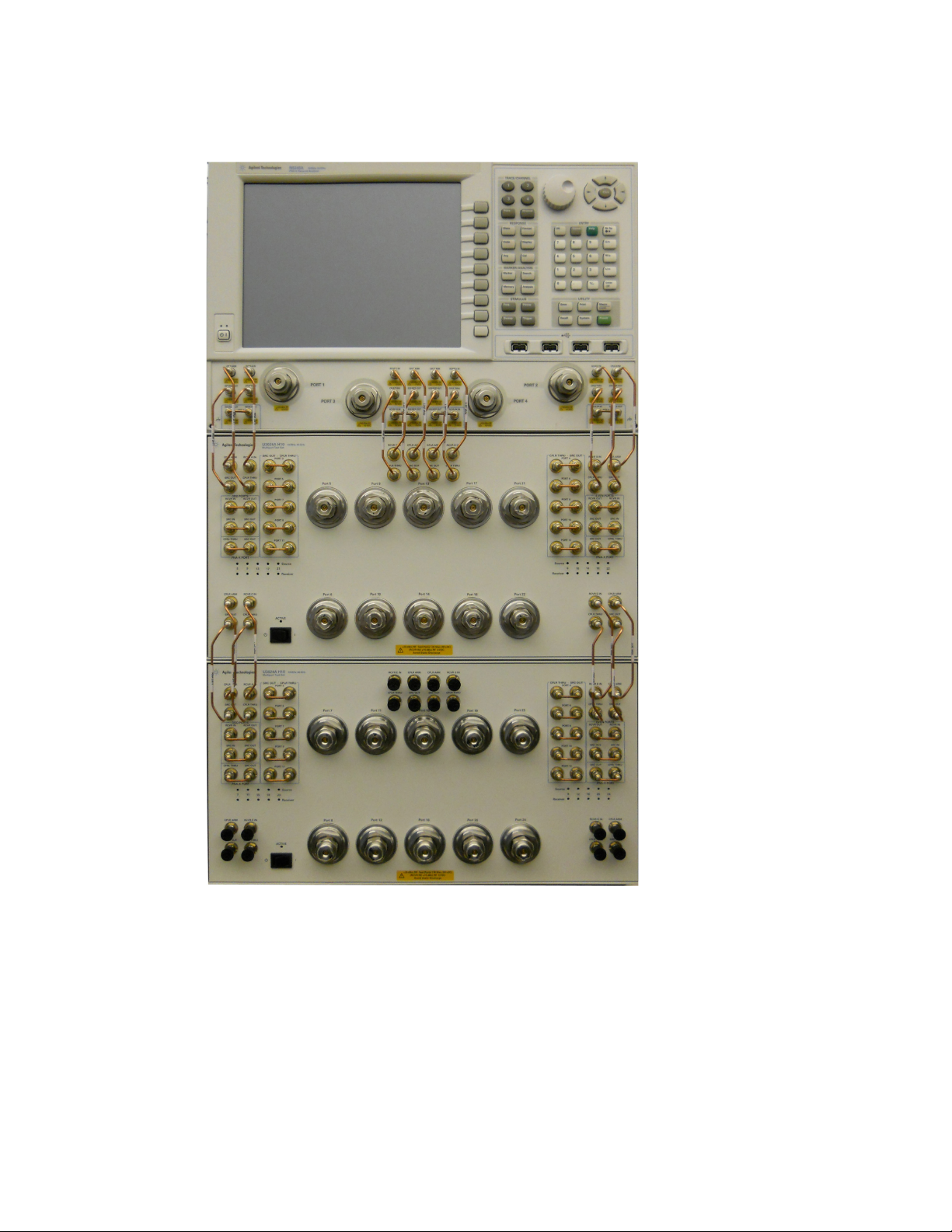
Figure 1 N5244/45A 4-Port PNA-X with 14-Port Configuration
1
Keysight U3024AH10 User's and Service Guide

Figure 2 N5244/45A 4-Port PNA-X with 24-Port Configuration
Keysight U3024AH10 User's and Service Guide
2

Description
The Keysight U3024AH10 is a Multiport Test Set Extension designed to be configured for high
power measurements in either a 14 or 24-Port network analyzer measurement system. Two
U3024AH10 Test Sets are required for the 24-Port network analyzer system, as shown in
Figure 2, page 2. The Keysight U3024AH10 has the following key features:
•10 Test Ports (2.4 mm male connectors)
•Low-loss mechanical RF switching
•High-powered device measurement capability
•N-Port calibration and full cross bar measurement capability
•Frequency range of operation: 10 MHz - 40 GHz (Standard Opt 700)
•Keysight PNA-X compatibility with rear panel Test Set I/O interface for operational control.
The PNA Option 551 is required. An external personal computer is not required.
The Keysight N5224A/B, N5225A/B, N5244A/B, and N5245A/B PNA/PNA-X
Network Analyzers will be referred to throughout this document as the PNA-X.
The U3024AH10 will be referred to as the Test Set.
Measurement Application Notes
Low Loss DUT Measurements
Low loss trace ripple is a product of switch repeatability and calibration technique. Low
insertion loss measurements exhibiting a 0.1 dB uncertainty ripple residing on the
measurement response is not uncommon.
Switch Configuration Command Speed
When writing address and data values to the test set directly, include a 15ms wait before
issuing another address and data set. The delay of 15ms is required for the test set internal
switches to settle. Failure to add the delay could cause the test set internal switches to stick
or cause intermittent failures.
Table 1U3024AH10 Accessories Supplied
Description
Short, Coax 2.4 mm female 85056-60021
Part Number
RF Cable, Semi-rigid, Front Panel Jumper N5245-20155
Guard, Jumper Cable - Side N5242-00029
Guard, Jumper Cable - Center N5247-00019
User's and Service Guide, U3024AH10 U3024-90001
Quantity
1
16
2
2
1
Lock-Links 1600-1423 4
1
1
1
1
1. These items are attached to the front of the Test Set at the factory.
3
Keysight U3024AH10 User's and Service Guide

Verifying the Shipment
To verify the contents shipped with your product, refer to the “Box Content List” included with
the shipment.
Inspect the shipping container. If the container or packing material is damaged, it should be
kept until the contents of the shipment have been checked mechanically and electrically. If there is
physical damage, refer to “Contacting Keysight” on page 99. Keep the damaged shipping
materials (if any) for inspection by the carrier and an Keysight Technologies representative.
Network Analyzer Requirements
All network analyzers require Option 551 to be installed for multiport operation (N-Port error
correction and measurement capability). Table 2 provides a listing of other network analyzer
option requirements. In order for the measurement system to cover the full frequency range of the
Test Set option listed, the network analyzer's frequency range should equal or exceed that of the
Test Set.
Table 2PNA-X Configuration Requirements
4-Port Network Analyzer
u3024ah10_pnax_p4.tsx
Test Set File
* The image shows two Test Sets configured in a 24-Port measurement system.
u3024ah10_x2_pnax_p4.tsx
System Figure
Options
N5224/25A/B
N5244/45A/B 400
1
2*
The Test Set files indicated in Table 2 above must be installed into this network analyzer file
directory location: c:/Program Files/Agilent/Network Analyzer/testsets.
Ensure the network analyzer has the latest version of firmware installed. The following website link
will provide the necessary information: http://na.support.keysight.com/pna/firmware/firmware.html.
Definitions
•Specifications describe the performance of parameters covered by the product warranty
(temperature –0 to 55 °C, unless otherwise noted.)
•Typical describes additional product performance information that is not covered by the
product warranty. It is performance beyond specification that 80% of the units exhibit with a
95% confidence level over the temperature range 20 to 30 °C. Typical performance does not
include measurement uncertainty.
•Nominal values indicate expected performance or describe product performance that is
useful in the application of the product, but is not covered by the product warranty.
•Characteristic Performance describes performance parameter that the product is expected to
meet before it leaves the factory, but is not verified in the field and is not covered by the
product warranty. A characteristic includes the same guard bands as a specification.
Keysight U3024AH10 User's and Service Guide
4

Available Options
Test Set Options
•700 -Standard, 10 MHz to 40 GHz frequency range, mechanical switches.
Front Handle and Rack Kits
•U3024AH10-1CM Front Rack Mount Flange Without Handles (5063-9216)
•U3024AH10-1CN Front Handles (5063-9229)
•U3024AH10-1CP Front Rack Mount Flange With Handles (5063-9223)
Network Analyzer Interface Kit Options
Table 3 below lists the Interface Kit Options required for a 14 or 24-Port PNA-X system. An
Interface Kit includes both the hardware Lock-Link and the RF interface cables to interface
the two instruments. Individual Lock-Link and Cable Kit numbers are shown for reference.
Table 3 Cable Kit Options
14-Port System
Hardware
Lock-Link Kit
Cable Kit, Connector Type
Interface Kit Option
N5224/25A/B PNA-X, Opt 400
N5244/45A/B PNA-X, Opt 400
U3021PX2 Opt H45
24-Port System
U3021-60002 U3024-60001, 2.4 (m)/(m)
12
N5224/25A/B PNA-X, Opt 400
N5244/45A/B PNA-X, Opt 400
U3021PX2 Opt H45
U3040AC01 Opt 001
U3021-600023U3024-60001, 2.4 (m)/(m)4
U3040-60001, 2.4 (m)/(m)4
1. Refer to "14-Port System Setup" on page 15.
2. Refer to "14-Port System Interface Cable Connections" on page 18.
3. Refer to "24-Port System Setup" on page 20.
4. Refer to "24-Port System Interface Cable Connections" on page 24.
An additional expanded 24-Port System configuration is also available. The 24-Port System can be
expanded by adding two U3040AS84 Test Sets. To accommodate a >24-Port expanded system,
order User Interface Options U3021PX2-H45, U3040AC01-001, and U3040AC01-002. Refer to the
U3040-90002 Service Note for more details regarding this system.
and
5
Keysight U3024AH10 User's and Service Guide
Table des matières
Autres manuels Keysight Technologies Matériel réseau
Manuels Matériel réseau populaires d'autres marques

Matrix Switch Corporation
Matrix Switch Corporation MSC-HD161DEL Manuel utilisateur

B&B Electronics
B&B Electronics ZXT9-IO-222R2 Manuel utilisateur

Yudor
Yudor YDS-16 Manuel utilisateur

D-Link
D-Link ShareCenter DNS-320L Manuel utilisateur

Samsung
Samsung ES1642dc Instructions d'utilisation

Honeywell Home
Honeywell Home LTEM-PV Instructions de montage