Ketra X 2 Manuel utilisateur
X2
KEYPAD
Instlltion Guide
Model
X2-ND KetraNet Mesh Keypad 120277 V~
X2-INC KetraNet Mesh + 600 W Incandescent Dimmer 120 V~

Risk of electric shock. Use in dry locations only.
Turn power OFF at circuit breker or remove fuse. Dmge to this product cused by wiring with power
on voids the wrrnty.
Due to the risk of electric shock, a licensed electricin should instll this power supply unit in strict
complince with the Ntional Electricl Code nd ny stte or locl code which my pply.
This device complies with Part 15 of the FCC Rules. Operation is subject to the
following two conditions: ( 1 ) this device may not cause harmful interference, and ( 2 ) this device must
accept any interference received, including interference that may cause undesired operation.
Note: This equipment has been tested and found to comply with the limits for a Class B digital device,
pursuant to part 15 of the FCC Rules. These limits are designed to provide reasonable protection against
harmful interference in a residential installation. This equipment generates, uses and can radiate radio
frequency energy and, if not installed and used in accordance with the instructions, may cause harmful
interference to radio communications. However, there is no guarantee that interference will not occur
in a particular installation. If this equipment does cause harmful interference to radio or television
reception, which can be determined by turning the equipment o and on, the user is encouraged to try
to correct the interference by one or more of the following measures:
• Reorient or relocate the receiving antenna.
• Increase the separation between the equipment and receiver.
• Connect the equipment into an outlet on a circuit dierent from that to which the receiver
is connected.
• Consult the dealer or an experienced radio/TV technician for help
This device contains licence-exempt transmitter(s)/receiver(s) that comply with Innovation, Science and
Economic Development Canada’s licence-exempt RSS(s). Operation is subject to the following
two conditions:
• This device may not cause interference.
• This device must accept any interference, including interference that may cause undesired
operation of the device.
!Wrning
2|X2 INSTALLATION GUIDE
770-000026-01 r12
© 2019 Ketra, Inc. All rights reserved

Contents
Product Overview 4
Included Components/Specs 5
Specifications 5
Dimension Drawings 6
Dimmer Load 7
Wiring Diagrams 8
Installation 10
X2-ND AC Input, Non-dimming 10
Retrofit Important Notes 12
Retrofit Instructions 12
X2-INC Incandescent Dimmer 13
Retrofit Important Notes 15
Replacing Button Chassis 16
Operation 17
Warranty Tech Support 18
3|X2 INSTALLATION GUIDE
770-000026-01 r12
© 2019 Ketra, Inc. All rights reserved

Product Overview
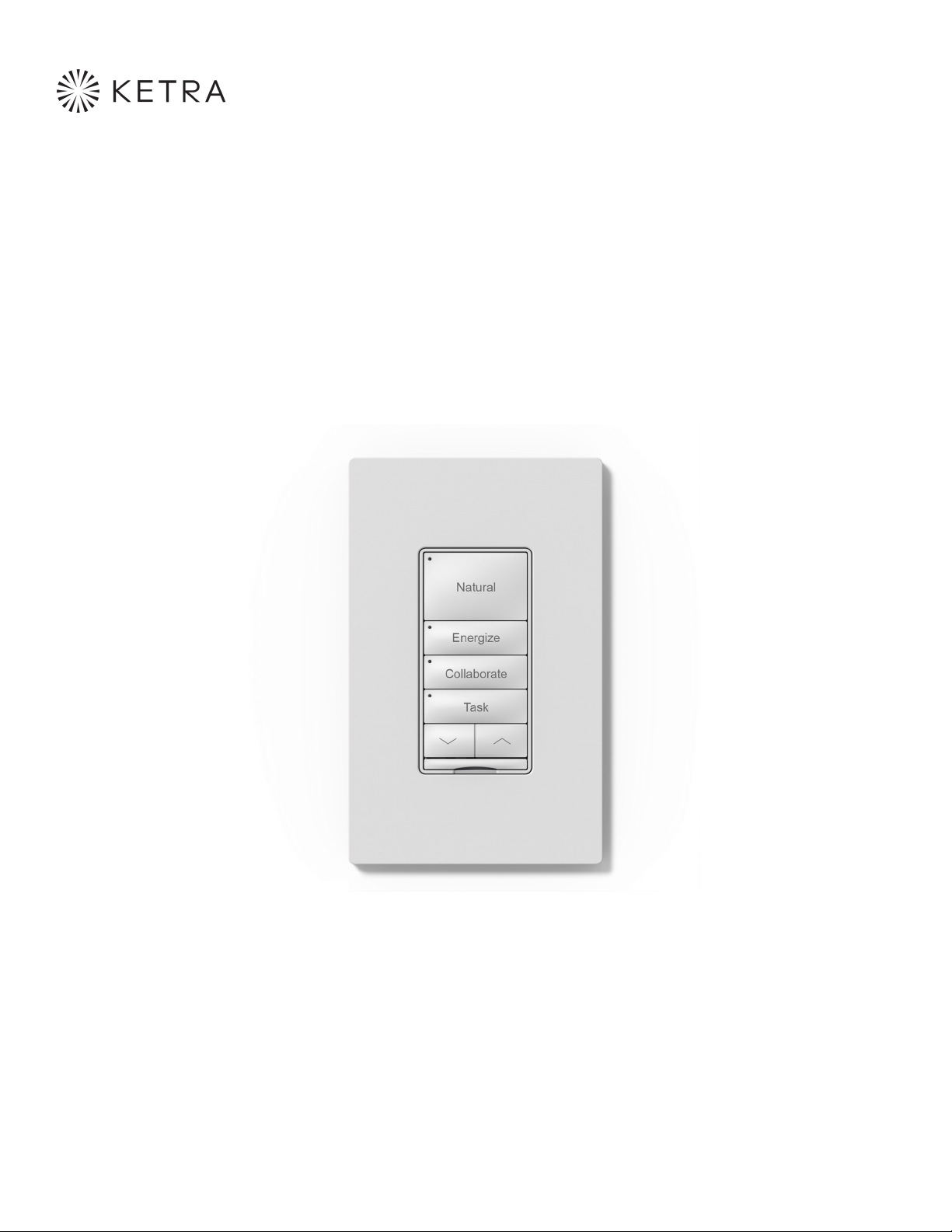
Ketra’s X2 keypad oers users a classic button-style interface for the
complete control of a lighting system.
X2s come in two models: a wireless KetraNet Mesh controller and a wireless KetraNet
Mesh controller with onboard incandescent dimmer. The latter is ideal for spaces where
both Ketra and traditional lighting sources need to be controlled. Fitting within a
standard wall box and either Decora® or Claro wall plates, the X2 is perfect for retrofit
installations as well as new construction.
fig. 1
Backbox X2 With
Button Chassis
X2 Mounting
Screws
Wall Plate
Mounting Screws
Wall Plate Mount Single Gang
Wall Plate
4|X2 INSTALLATION GUIDE
770-000026-01 r12
© 2019 Ketra, Inc. All rights reserved

Included Components/Specs
Specifications
X2 with button chassis
( 2 ) #632 × 0.75 in (6.35 mm)
wall plate mounting screws
Serial number stickers
Wall plate mount
( 2 ) #632 × 1 in (25.4 mm)
X2 mounting screws
Wire nuts
Single gang wall plate
Environmental
Ambient Operating
Temperature
0° to 40°C
Storage Temperature -20˚ to 80 ˚C
Humidity 095%, Non-condensing
Certification UL, cUL, FCC Class B, RoHS
Location UL Damp Location, IP20
Mechanical
Weight 8.8 oz/250 kg
Housing Material Flame Retardant Polymer
Wireless
Frequency 24052480 MHz
Output Power 1820 dBm
Electrical
Input Wiring 16 AWG Flying Leads
Voltage X2.ND 120277 VA
X2.INC 120 V
Power Consumption 2 W
Frequency 50/60 Hz
X2.ND.AC
SN: KX12345678
DC: V0216
X2.D.ELV
SN: KX12345678
DC: V0216
5|X2 INSTALLATION GUIDE
770-000026-01 r12
© 2019 Ketra, Inc. All rights reserved

Dimension Drawings
4.1 in
(105 mm)
2.6 in
(66.23 mm)
1.4 in
(35.3 mm)
3.3 in
(83.6 mm)
0.3 in (7.6 mm)
0.2 in (6.1 mm)
1.3 in
(32.98 mm)
1.7 in (43.97 mm)
multi-gang trim
2.4 in
(60.15 mm)
6|X2 INSTALLATION GUIDE
770-000026-01 r12
© 2019 Ketra, Inc. All rights reserved

Dimmer Load
X2-INC Load Type and Capacity Chart
Load Type Single Gang Multigang
Incandescent 600 W 500 W
Dimmer capacity rated at 25 ˚C ambient temperature; derate incandescent and halogen loads an additional
100 W at 40 ˚C temperature ambient.
7|X2 INSTALLATION GUIDE
770-000026-01 r12
© 2019 Ketra, Inc. All rights reserved

Wiring Diagrams
X2 Keypad
X2 ND
X2 INC X2 ND
LOAD
LOAD
BlackHot/Line
Hot/Line
Hot/Line
Hot/Line
Red Black
Black White
White Green
Traveler 2
(not used)
Green
Hot/Line
120277 V
50/60 Hz
WhiteNeutral
Neutral
Neutral
Ground Ground
GreenGround
Ground
Ground
Traveler 1 Traveler 1
Traveler 2 Traveler 2
3-way
switch
3-way
switch
X2 Keypad, AC
input, no dimmer
X2 Keypad,
INC dimmer
Switch - Load + Switch
X2 Keypad Ketra Retrofit
Switch - Load + Switch
3-Way Switch
8|X2 INSTALLATION GUIDE
770-000026-01 r12
© 2019 Ketra, Inc. All rights reserved

WIRING DIAGRAMS
X2 INC X2 ND
LOAD
LOAD
Hot/Line
Hot/Line
Hot/Line Hot/Line
Red
Black
Black
White
White
Traveler 2
(not used)
Green
Green
Neutral
Neutral
Ground Ground
Ground
Ground
Traveler 1 Traveler 1
Traveler 2 Traveler 2
3-way
switch
3-way
switch
X2 Keypad, AC
input, no dimmer
X2 Keypad,
INC dimmer
Load - Split Switches
3-Way Switch
Load - Split Switches
X2 Keypad Ketra Retrofit
9|X2 INSTALLATION GUIDE
770-000026-01 r12
© 2019 Ketra, Inc. All rights reserved

Installation
X2-ND AC Input, Non-dimming
New Construction
1. Install wall box (single gang wall box with at least 14 in volume only).
2. If installing in a multigang box, the side-fins must be removed for fit (see figures 2 and 3).
3. Run power to wall box utilizing stranded or solid core 1218 AWG wire (see figure 4).
4. Prepare the wire for connection to lead wire: A. Strip 8.5 mm of wire for insertion into the wire nut.
B. Twist the stranded wire to prevent fraying (tinning optional).
5. Using the provided wire nuts, attach each X2 lead wire to the corresponding conductor. Black-Line,
White-Neutral, Green-Ground (see figure 5).
fig. 2
fig. 4
fig. 3
fig. 5
continued on next page
10|X2 INSTALLATION GUIDE
770-000026-01 r12
© 2019 Ketra, Inc. All rights reserved
Autres manuels pour X 2
2
Table des matières
Autres manuels Ketra Clavier


