KBR multicomp F144-MS-1V1C1TI6RO-3 Manuel utilisateur
25359_EDEBDA0279-2320-1_EN
User manual
Technical Parameters
System IEnglish
4-quadrant controller
multicomp
F144-MS-1V1C1TI6RO-3
F144-MS-1V1C1TI12RO-3

V2.01
25359_EDEBDA0279-2320-1_EN
2
1 Introduction ....................................................................................................................................4
1.1 User Manual.....................................................................................................................................4
1.3 Safety Notes.....................................................................................................................................6
1.4 Product Liability.............................................................................................................................7
1.5 Disposal.............................................................................................................................................7
1.6 Overvoltage and Lightning Protection..................................................................................7
2 Functional Principle of the Controller....................................................................................8
3 Control and Display Panel ........................................................................................................10
4 Setting Range of the Congurable Parameters:...............................................................14
5 Installation and Electrical Connection of the System.....................................................16
5.1 General, very important information...................................................................................16
5.2 Current transformer connection and measuring voltage.............................................16
5.3 Current transformer dimensions............................................................................................16
5.4 Standard connection diagram................................................................................................17
5.5 Measuring voltage connection Ph-N....................................................................................18
5.6 Measuring voltage connection Ph-Ph .................................................................................19
Table of Contents
KBR Kompensationsanlagenbau GmbH does not accept any liability for any loss
or damage resulting from printing errors in or changes to this manual.
In addition, KBR Kompensationsanlagenbau GmbH does not accept any liability for
any loss or damage caused by defective devices or devices manipulated by the user.
Copyright 2020 by KBR Kompensationsanlagenbau GmbH
Subject to change.
Table of contents

V2.01
25359_EDEBDA0279-2320-1_EN
3
6 Commissioning the System.....................................................................................................20
6.1 General notes on commissioning..........................................................................................20
7 Navigation and Device Displays.............................................................................................22
8 Device displays of the main menus ......................................................................................24
9 Description of the individual display windows ................................................................26
9.1. Initialization window:.................................................................................................................26
9.2 Commissioning window if no stage power is programmed........................................26
9.3 Start menu window:...................................................................................................................29
9.4 Stage state window:...................................................................................................................31
9.5 Service window:...........................................................................................................................32
9.6 Commissioning window:..........................................................................................................33
9.7 Switching performance window: ..........................................................................................35
10 Notes on Troubleshooting........................................................................................................42
11 System and Safety Device Maintenance.............................................................................43
12 Technical Data...............................................................................................................................44
12.1 Measuring and display values.................................................................................................44
12.2 Measuring accuracy....................................................................................................................45
12.3 Measuring principle....................................................................................................................45
12.4 Device memory............................................................................................................................45
12.5 Limits:...............................................................................................................................................45
12.6 Power supply.................................................................................................................................45
12.7 Hardware inputs and outputs.................................................................................................46
12.7.1 Hardware inputs...........................................................................................................................46
12.7.2 Hardware outputs ......................................................................................................................46
12.8 Electrical connection..................................................................................................................47
12 Selection of cables and fuses ..................................................................................................49
14 Data Point Description for the Modbus Protocol.............................................................50
14.1 Modbus commands supported..............................................................................................51
14.2 Data formats..................................................................................................................................51
14.3 Interface parameters..................................................................................................................54
14.4 Device settings.............................................................................................................................54
14.5 Data points.....................................................................................................................................60
15 Device information .....................................................................................................................63
Table of contents

V2.01
25359_EDEBDA0279-2320-1_EN
4
1 Introduction
Thank you for choosing this KBR quality product.
To become familiar with the operation and programming of the device and to use the
full range of functions of this high-quality product at all times, you should read this user
manual carefully.
The individual chapters explain the technical details of the device and show how damage
can be avoided through proper installation and commissioning.
1.1 User Manual
This user manual describes the device version multicomp F144-3. This user manual must
be accessible to the user at all times (e.g. in the switchgear cabinet). Even if the device is
resold to third parties, the manual remains an inherent part of the device.
Although the utmost care has been taken in writing this user manual, errors may still oc-
cur. We would be very grateful if you would notify us of any errors or unclear descriptions
you may notice.
Introduction

V2.01
25359_EDEBDA0279-2320-1_EN
5
1.2 Safety Keys
This manual contains instructions that you must follow for your personal safety and to
avoid material damage. These instructions are identied by a warning sign or information
symbol, depending on the degree of hazard they warn about.
DANGEROUS VOLTAGE
„Warning“ means that death, major injuries or damage may occur if suitable safety pre-
cautions are not taken.
CAUTION
„Caution“ means that minor injuries or damage may occur if the appropriate safety pre-
cautions are not taken.
NOTE
„Note“ is an important piece of information on the product, its operation or the respec-
tive part of the operating instructions to which special reference is being made.
Disclaimer
The contents of these operating instructions have been carefully reviewed in terms of
the hardware and software described. Nonetheless, deviations cannot be ruled out, and
the manufacturer cannot guarantee 100% conformity. The specications made in these
operating instructions are reviewed on a regular basis; any corrections required will be
included in the next revision.
Introduction

V2.01
25359_EDEBDA0279-2320-1_EN
6
1.3 Safety Notes
In order to prevent operating errors, device operation is kept as simple as possible. This
will enable you to start your device up quickly.
It is in your own interest to read the following safety instructions carefully. The applicable
DIN/VDE regulations must be observed for installation!
Power supply connection, setup and operation of the device must be performed by
qualied personnel only. Qualied personnel as dened in the safety notes in this user
manual are those authorized to set up, ground and mark devices, systems and circuits in
accordance with applicable standards and regulations.
To prevent re and electric shock, do not expose the device to rain or moisture!
Before connecting the device to the power supply, check whether the local power supply
conditions comply with the specications on the device nameplate.
CAUTION
Incorrectly connecting the device can damage it.
For device connection, the data given in the connection diagram must be complied with
(see chapter“Connection diagram”) and the connection lines must be voltage-free. When
wiring, always ensure that all wiring material used is neither damaged nor defective and
that the polarity is correct!
Proper and safe operation of the product requires correct transport, storage, installation
and assembly as well as careful operation and maintenance.
If the device has any visible damage it is considered unt for use and must be disconnect-
ed from the power supply!
Troubleshooting, repairs and maintenance work may only be carried out at our plant or
after contacting our customer service team. If the device is opened without authoriza-
tion, any warranty or guarantee claim is forfeited. Correct functioning can no longer be
guaranteed!
Opening the device may expose live parts. Capacitors in the device may still be charged,
even if the device has been disconnected from all power sources. Do not operate open
devices under any circumstances!
Systems that are at risk from lightning strikes must feature lightning protection for all
input and output lines.
Introduction

V2.01
25359_EDEBDA0279-2320-1_EN
7
1.4 Product Liability
You have purchased a high-quality product. Only top-quality components with excep-
tional reliability are used.
Each device undergoes a long-term test before delivery.
With regard to product liability, please see our general terms and conditions for electron-
ic devices, which you can read at www.kbr.de.
The warranty on device characteristics only applies if the device is operated in accor-
dance with its intended use!
1.5 Disposal
Please dispose of defective, out-of-date or no longer used devices properly.
If required, we will dispose of the device for you.
1.6 Overvoltage and Lightning Protection
To protect your purchased high-quality devices from damage, we strongly recommend
that you take overvoltage protection measures. Protect control voltage inputs, pulse and
bus lines.
Introduction

V2.01
25359_EDEBDA0279-2320-1_EN
8
Functional principle
2 Functional Principle of the Controller
The controller's microprocessor records the mains voltage and current consumption of
the entire plant by measuring transformer inputs (A/D converter) and, on the basis of this,
calculates the active and reactive power ratio of the mains. The controller operates in four
quadrants.
Energy recovery in generator operation is detected and indicated by a "G" ashing
on the LCD display. During this time, compensation to cos phi 1.00 (output cos phi) is
performed. To prevent alternating switching operations, this target cos phi is main-
tained for 15 minutes after generator operation.
The compensated power required for the target cos phi is calculated continuously. If the
power dierence corresponds to the set hysteresis (switch-on and switch-o hysteresis),
the stages are switched depending on the required compensation power. Manually
switched stages are, however, not included in the optimization. In case of identical
stages with identical power, the stage that has been switched o for the longest time is
switched on.
Having fewer switching operations results in optimum adjustment. Even for large sys-
tems, sensitive controls can be set up with just a few modules. Stage ratios do not need to
be considered. After compensation, switching operations are interrupted for a cong-
urable time. To prevent alternating switching operations, you can increase the stage
switch-o delay by up to 150% of the smallest stage's power.
In low load operation (secondary measuring current under the limit), the stages are
switched o after the set delay time.
The integrated temperature measurement input monitors the temperature in the reactive
power Compensation system and causes the fan to be switched on if a predened
temperature threshold is exceeded and switched o again when the temperature drops
below the reset temperature.
To prevent the fan from switching unnecessarily often, it has a run-on time of 30 minutes.
You can switch the fan (relay output 6 or 12 depending on the device version) on or o
permanently using the "Stage status" menu. If you select "Auto", the fan output is con-
trolled by the temperature measuring input.
You can also protect the system by dening a switch-o temperature. This makes it pos-
sible to switch stages o in time if there is a risk of damage due to overheating. Once the
temperature drops below the reset temperature, the stages are switched on again one
after the other.

V2.01
25359_EDEBDA0279-2320-1_EN
9
Functional principle
The settings are saved on an EEPROM so that they are not lost in the event of a power
failure.
The measuring cycle of the controller used to record the necessary network parameters
takes approx. 20 ms.
NOTE
Limit for overvoltage switch-o = measuring voltage + 10% (taking the measuring volt-
age ratio into account). This value cannot be changed and serves to protect the compen-
sation system.
In the event of an error, the compensation stages are switched o. The alarm relay switch-
es and "Overvoltage" is displayed.
CAUTION
The discharge times are automatically predened for the following programmed stage
powers. However, these must be checked and corrected if they dier from the capacitor
specications.
Capacitor power Discharge resistance Discharge time
0.1 kvar – 9.9 kvar 300 kOhm 60 seconds
10 kvar – 19.9 kvar 300 kOhm 120 seconds
20 kvar and above 300 kOhm 180 seconds

V2.01
25359_EDEBDA0279-2320-1_EN
10
Control and display panel
1
2
3 4
1
2
3 4
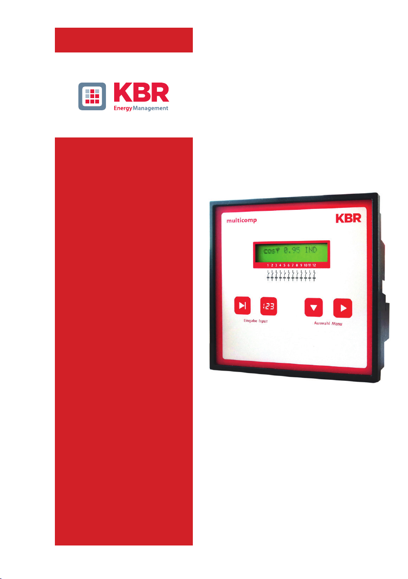
3 Control and Display Panel
Operating elements:
1 LCD displaying the current status and user prompts
2 Number of possible controller output lines
3 Two sensor buttons for parameter conguration
4 Two sensor buttons for menu selection
multicomp F144-3 Eco 6-stage
multicomp F144-3 Eco 12-stage
Ce manuel convient aux modèles suivants
1
Table des matières
Autres manuels KBR Contrôleurs

KBR
KBR F144-MS-1V1C6-12DO-3 Manuel utilisateur

KBR
KBR multicomp 4D6-ESBSDS-1V1C6RO Mode d'emploi

KBR
KBR multicomp F144-NC-1V1C6DO6RO-2 Manuel d'utilisation et d'entretien

KBR
KBR multicomp D6 7 Series Manuel utilisateur

KBR
KBR multicomp F144-MS-1V1C1TI6RO6DO-3 Manuel utilisateur

KBR
KBR multimax D6-5 Series Manuel utilisateur

KBR
KBR F144-3PH Manuel utilisateur

KBR
KBR multicomp D6 Series Manuel d'instructions

KBR
KBR multicomp F144-MS-1V1C1TI6DO6RO-3 Manuel de service

KBR
KBR Multicomp 2F144-NC-1V1C06RO Mode d'emploi


