Joie i-Spin 360 Manuel utilisateur
i-Spin 360
enhanced child restraint
ECE R129/02
Rearward Facing:
Child height 40cm-105cm/ Child weight 19kg;
Forward Facing:
Child height 76cm-105cm/ Child weight 19kg;
ECE R129/02: ISO/F2X, ISO/R2
ECE R129/02: i-Size
Instruction Manual
Manual de instruções
Manual de instrucciones
Mode d’emploi
Handleiding
GB
PT
ES
FR
NL
1
Welcome to Joie™
Congratulations on becoming part of the Joie family! We are so excited
to be part of your journey with your little one. While traveling with the
i-Spin 360 enhanced child restraint you are using a high quality, fully
certified safety i-Size enhanced child restraint. Please carefully read this
manual and follow each step to ensure a comfortable ride and best pro-
tection for your child.
To use this Joie enhanced child restraint with the i-Size ISOFIX connec-
tions according to the ECE R129/02 Regulation, your child must meet
the following requirements.
Rearward Facing: Child height 40cm-105cm/ Child weight 19kg;
Forward Facing: Child height 76cm-105cm/ Child age at least 15 month
/Child weight 19kg;
Base
Please read all the instructions in this manual before installing and us-
ing the product.
! IMPORTANT: KEEP FOR FUTURE REFERENCE.
PLEASE READ CAREFULLY.
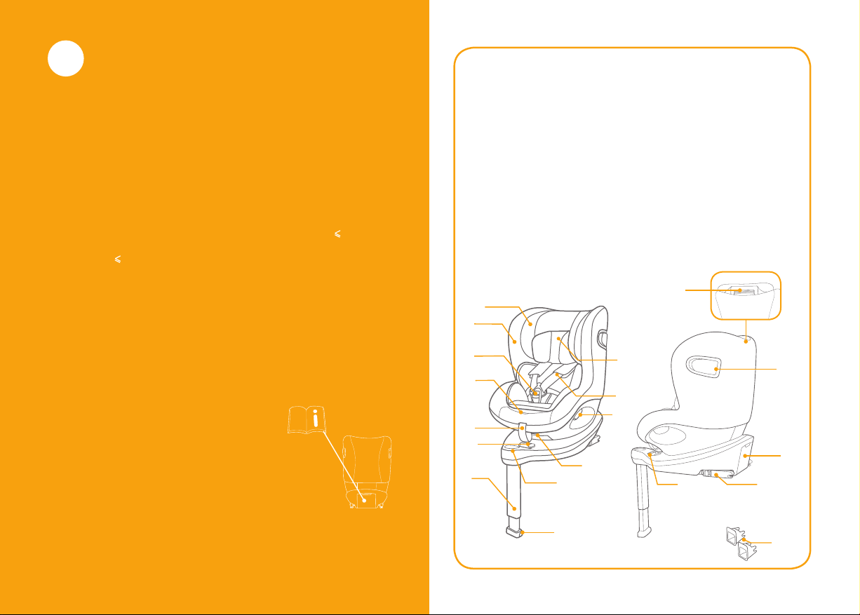
Please keep the instruction manual in the
storage compartment at the back of
the base as right figure.
For warranty information, please visit our
website at joiebaby.com
Parts List
Fig. 1 Head Support
Fig. 2 Seat Pad
Fig. 3 Buckle
Fig. 4 Harness Adjustment
Button
Fig. 5 Adjustment Webbing
Fig. 6 Smart Ride™ lock-off
Fig. 7 Load Leg
Fig. 8 Load Leg Adjustment
Button
Fig. 9 Load Leg Indicator
Fig. 10 Recline Adjustment
Button
Fig. 11 Rotating Button
Fig. 12 Shoulder Strap
Fig. 13 Infant Insert
Fig. 14 Head Support
Adjustment Lever
Fig. 15 Side Impact Shield
Fig. 16 Instruction Manual
Storage Compartment
Fig. 17 ISOFIX Connector
Fig. 18 ISOFIX Adjuster
Button
Fig. 19 ISOFIX Guides
Please make sure there are no missing parts. Please contact the
retailer if anything is missing.
GB
1
2
3
4
10
9
12
17
18
14
5
6
8
11
15
16
7
19
13

3 4
WARNING
!To use this enhanced child restraint with the ISOFIX
connections according to the ECE R129/02 Regula-
tion, your child must meet the following requirements.
Rearward Facing:
Child height 40cm-105cm/ Child weight 19kg;
Forward Facing:
Child height 76cm-105cm/ Child age at least 15 month
/Child weight 19kg;
!IMPORTANT - DO NOT USE FORWARD FACING
BEFORE THE CHILD’S AGE EXCEEDS 15 months
(Refer to instructions)
!Any straps holding the enhanced child restraint to the
vehicle should be tight, that any support-leg should
be in contact with the vehicle floor, that any straps
restraining the child should be adjusted to the child’s
body, and that straps should not be twisted.
!After your child is placed in this enhanced child
restraint, the safety belt must be used correctly, and
ensure that any lap strap is worn low down, so that
the pelvis is firmly engaged, shall be stressed.
!This enhanced child restraint should be replaced when
it has been subject to violent stresses in an accident.
An accident can cause damage to them that you
cannot see.
WARNING
!Concern the danger of making any alterations or
additions to the device without the approval of the
competent authority, and a danger of not following
closely the installation instructions provided by the
enhanced child restraint manufacturer.
!Please keep this enhanced child restraint away from
sunlight, otherwise it may be too hot for child’s skin.
Always touch the enhanced child restraint before
placing child in it.
!Child is not left in the enhanced child restraint system
unattended.
!Any luggage or other objects liable to cause injuries in
the event of a collision shall be properly secured.
!The enhanced child restraint shall not be used without
the soft goods.
!The soft goods should not be replaced with any other
than the one recommended by the manufacturer,
because the soft goods constitutes an integral part of
the restraint performance.
!DO NOT use any load bearing contact points other
than those described in the instructions and marked
on the enhanced child restraint.

5 6
WARNING
!NEVER install this enhanced child restraint on any
vehicle seat equipped with safety airbags when used
with babymode.
!Please check before you purchase this enhanced
child restraint to make sure it can be installed prop-
erly in your vehicle.
!NO enhanced child restraint can guarantee full protec-
tion from injury in an accident. However, proper use of
this enhanced child restraint will reduce the risk of
serious injury or death to your child.
!DO NOT install this enhanced child restraint without
following the instructions in this manual or you may
put your child at serious risk of injury or death.
!DO NOT use this enhanced child restraint if it has
damaged or missing parts.
!DO NOT have your child in large/oversized clothes
because this may prevent your child from being
properly and securely fastened by the shoulder
harness straps and the crotch strap between the legs.
!DO NOT leave this enhanced child restraint or other
items unbelted or unsecured in your vehicle because
an unsecured enhanced child restraint can be thrown
around and may injure occupants in a sharp turn, sud-
den stop, or collision.
WARNING
!NEVER use a second-hand enhanced child restraint
or an enhanced child restraint whose history you do
not know because it may have structural damage
that compromises your child’s safety.
!NEVER use ropes or any other substitutes to secure
enhanced child restraint in vehicle or to secure child
into enhanced child restraint.
!Be sure that the enhanced child restraint is installed
in such a way that no part of it interferes with
movable seats or in the operation of vehicle doors.
!Consult the distributor for issues concerning mainte-
nance, repair and part replacement.
!Remove this enhanced child restraint from the
vehicle seat when it is not in use for a long period of
time.
!The parts of this enhanced child restraint should not
be lubricated in any way.
!Always secure child in enhanced child restraint, even
on short trips, as this is when most accidents occur.
!Frequently check the ISOFIX guides for dirt and clean
them if necessary. Reliability can be effected by
ingress of dirt, dust, food particles etc.
!DO NOT put anything other than the recommended
inner cushions in this enhanced child restraint.
!The child restraint may not fit in all approved vehicles
when used in one of these positions.

7 8
Emergency
In case of emergency or accidents, it is most important to have your
child taken care of with first aid and medical treatment immediately.
Product Information
"i-Size" (Integral Universal ISOFIX Enhanced Child Restraint Systems)
is a category of Enhanced Child Restraint System for use in all i-Size
seating position of a vehicle.
1. According to the ECE R129/02 Regulation, the product is a Universal
ISOFIX Class ISO/F2X, ISO/R2 enhanced child restraint and should
be fitted using the ISOFIX connections.
2. This is an “i-Size” Enhanced Child Restraint System. It is approved
according to Regulation No.129, for use in, i-Size compatible vehicle
seating positions as indicated by vehicle manufacturers in the
vehicle users’ manual.
3. If in doubt, consult either the Enhanced Child Restraint System
manufacturer or the retailer.
Materials Plastics, metal, fabrics
Patent No. Patents pending
Concerns on Installation
1
24
3
57
6
1
24
3
57
6
1
2
3
A
I
R
B
A
G
2
1
see images 1- 2
910
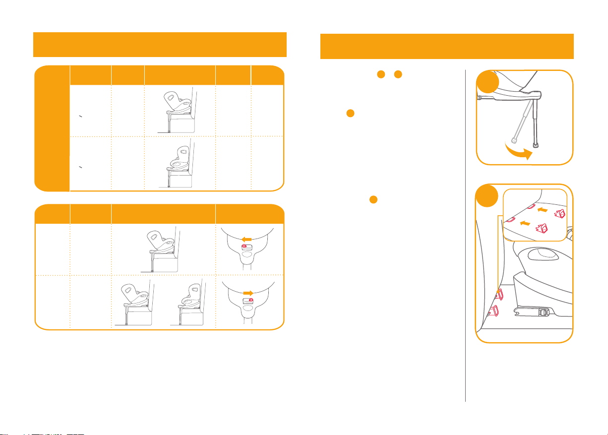
Installation
Mode InstallationReference
Age
Recline
Position
4 years
Position
Position
1 -6
Approx
1 -6
ECE
R129/02
40cm-105cm/
19kg
<
76cm-105cm/
19kg
<
Child's
Size
Rear
facing
mode
Forward
facing
mode
15 months
to approx
4 years
Choose the Installation Mode
Installation
Mode InstallationSmart Ride™ lock-o
0-15M
15M
or
<
Child's
Age
Rear
facing
mode
Rear/
Forward
facing
mode
Installing the Base
3
see images 3- 12
! After placing the base on the vehicle
seat, pull the load leg downward to
floor. 3
! Insert ISOFIX guides to assist with
installation. 4-1 41
11 12
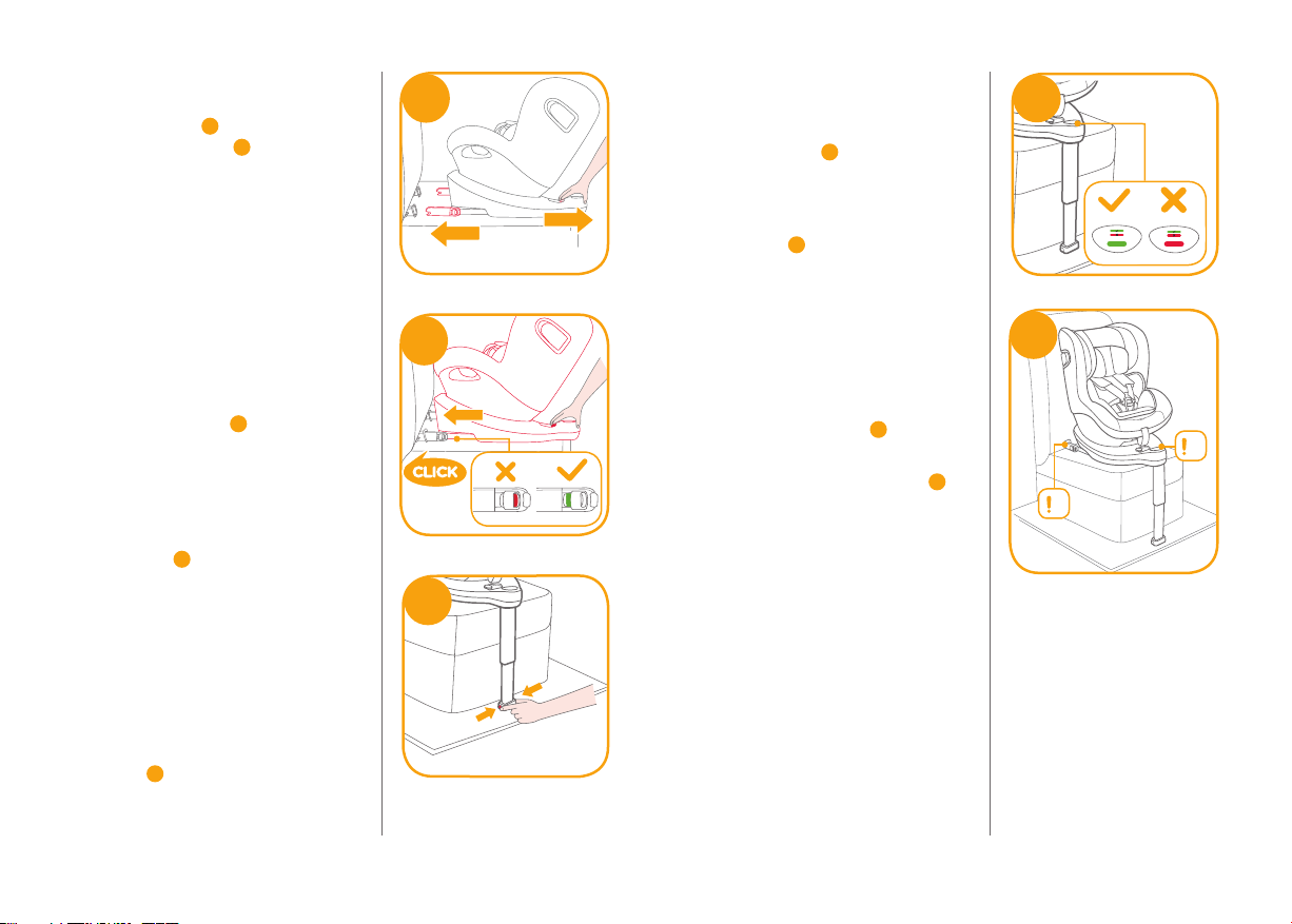
! There are 11 adjustable positions
for ISOFIX. Whilst depressing the
ISOFIX button 5-1, pull out the
ISOFIX connector. 5-2
! Make sure that both ISOFIX
connectors are securely attached
to their ISOFIX anchor points. The
colors of the indicators on both
ISOFIX connectors should be
completely green. 6-1
! After successfully installing the
ISOFIX connectors, press the
ISOFIX adjustment buttons again
while pushing the seat back until it
comes in contact with the vehicle
seat back. 6
! After attaching the ISOFIX, pull the
load leg downward to floor. When
the load leg indicator shows green,
the load leg is installed correctly.
! Squeeze the load leg releasing
button, then adjust the load leg
length. 7
5
1
2
1
6
7
!The load leg has 19 positions.
When the load leg indicator shows
red this means the load leg is in the
wrong position. 8
!Make sure the load leg is in full
contact with the vehicle floor pan.
Red means it is installed
incorrectly. 8
!Check to make sure the base is
securely installed by pulling on
both ISOFIX connectors.
!The ISOFIX connectors must be
attached and locked onto the
ISOFIX anchor points. 9-1
!The load leg must be installed
correctly with green indicator. 9-2
8
9
1
2
13 14
11
1
2
Removing the base
To remove from the vehicle press
the ISOFIX adjuster button 10 -1 and
pull the base back from the seat.
10 -2
Then press and release the
connectors from the vehicle’s
ISOFIX. 11
To prevent damage during transit,
press the ISOFIX adjuster button
12 -1 and fold the connector
completely. 12 -2
12
1
2
10
12
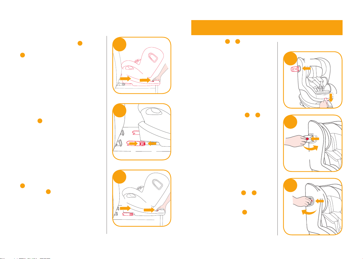
see images 13 - 15
!Ensure the side impact protection
shield is locked in the open
position for maximum side impact
safety.
1. Side impact shields are
automatically activated when the
harness buckle is moved back into
position and the harness is
tightened, both sides will be
opened automatically. 13 -1 13 -2
!IMPORTANT: Please note that
unfolding the side impact
protection elements does NOT
mean that the child is already
restrained tight enough.
2. The side impact shield opposite
the vehicle door can be closed to
allow more seating space, if
needed. The side closest to the
vehicle exterior should always be
in the open position. 14 -1 14 -2
3. The side impact can be manually
opened as shown on 15 .
Use Side Impact Shield
13
1
2
15
14
1
2
1
2

15 16
see images 16 - 17
Squeeze the recline adjustment
button 16 , to adjust the enhanced
child restraint to the proper position.
The recline angles are shown as 17
Please recheck the load leg position
after reclining.
There are 6 recline positions for rear
facing mode and 6 recline positions
for forward facing mode.
Recline Adjustment
16
17
Height Adjustment
for Head Support and Shoulder Harnesses
see images 18 - 20
1. Please adjust the head support
and check if the shoulder
harnesses are at the correct
height according to 18
!When used rear facing, the
shoulder harness height must be
even with or below the top of
child’s shoulders. 18
!When used forward facing, the
shoulder harness height must be
even with the top of child’s
shoulders.
18
2. Squeeze the head support
adjustment lever 19 , meanwhile
pull up or push down on the head
support until it snaps into one of
the 6 positions. The head support
positions are shown as 20 .
18
20
19
1
2

17 18
Using in the Rear Facing Mode
(Child height 40cm-105cm/Child weight
19kg/infant - 4 years old)
see images 21 - 32
!Please install the enhanced child
restraint on the rear vehicle seat,
and then put the child in the
enhanced child restraint.
!Please slide Smart Ride™
lock-off to left when enhanced
child restraint used in rearward
facing mode.
1. Press the ISOFIX adjuster button
22 -1 and pull the base back from
the vehicle seat.
2. Press the rotating button to rotate
for easier side loading/unloading
of the child, then rotate the seat
to the rear facing position. 23 &24
!Press the rotating button on either
side to rotate the enhanced child
restraint.
22
1
2
23
21
3. After successfully installing the
ISOFIX connectors, press the
ISOFIX adjustment buttons again
while pushing the seat back until
it comes in contact with the
vehicle seat back. 25 -1 25 -2
!The ISOFIX connectors must be
attached and locked onto the
ISOFIX anchor points. 26 -1
!The load leg must be installed
correctly with green indicator.
26 -2
25
1
2
24
26
2
1
Table des matières
Langues :
Autres manuels Joie Accessoires automobiles

Joie
Joie verso Manuel utilisateur

Joie
Joie i-Harbour Manuel utilisateur

Joie
Joie i-Snug Manuel utilisateur

Joie
Joie arc 360 Manuel utilisateur

Joie
Joie i-Anchor Advance Manuel utilisateur

Joie
Joie gemm Manuel utilisateur

Joie
Joie every stage Manuel utilisateur

Joie
Joie i-Venture R Manuel utilisateur

Joie
Joie stages C0925 Manuel utilisateur

Joie
Joie i-Gemm 2 Manuel utilisateur


