iPixel LED Light T-780K Manuel utilisateur

1
T-780K operation manual
一、T-780K system features:
1、The controller has 8 output ports, each port can carry up to 170/512/768 pixels(Different pixels for different
chips).
2、The controller port output two kinds of signal protocol: ①DMX512/1990 international standard protocol and
DMX512 extended protocol; ②SPI/TTL serial protocol.
3、The controller output port provides three protections to ensure that the controller output port is not burn out in
the case of short circuit or reverse connection in the controlled lamp.
4、Controller ID automatic/manual numbering function, which can be numbered together with multiple controllers,
or individual controller numbers.
5、The controller comes with built-in effects to test on-load luminaires (all supported by RGB/RGBW luminaires).
6、The controller has DMX512 write function and address test. The single port or all ports carry the DMX512 IC
write address and perform address test on the luminaire.
7. The communication between the controllers adopts the international standard TCP/IP network protocol. The
optional transmission rate supports 100M/Gigabit adaptation, and the transmission speed is more stable and
fast. The maximum transmission distance between each two controllers can reach 100 meters. More than this
distance can increase the switch or use fiber for long-distance transmission.
8、The controller provides an LCD screen display that shows the model, ID, and operating status of the controller.
9、When connected with our online video software LedPlayer for computer control, the connection status of the
controller is monitored in real time on the computer. Using the online video software LedPlayer for computer
control can realize: program timing playback, program segment selection, effect brightness adjustment, white
balance online adjustment, program playback speed adjustment, display text, picture loop playback, etc., which
greatly satisfy the customer's application and Multiple needs in debugging.
10 、The online video software LedPlayer comes with Gamma correction, which makes the color display more
delicate and vivid.

2
11、When the controller is connected to the computer, the IP address is set. The controller supports online and
offline integrated control. The online priority is the highest. When there is no online signal, it automatically
switches to the offline effect.
Note 1: The DMX/1903 IC on the controller can be controlled by MADRIX software. The maximum normal 3 unit (3
Univ) lamps per port, that is 3*170 pixels; multi-controllers combined into the largest control system
Compatible with 2048 units.
Note 2: The controller supports rack-mounting. If necessary, please contact the relevant business personnel before
placing an order.
二、Support chips:(Software select T-780K)
Support chips
Max. support
light
Reamrks
International standard DMX512(like: UCS512, SM512, TM512,
GS512 etc)
4096 pixels
Suggest to carry 2400
pixels
UCS19**,ucs29**,ucs89**,ucs1603,ucs5603(UCS full series
TTL/SPI signal IC)
6144 pixels
Suggest to carry 4096
pixels
SM16703,09,12,SM16716,16726(SM full series TTL/SPI signal IC)
6144 pixels
——
TM18** series, TM19** series
6144 pixels
——
WS28**(WS full series TTL/SPI signal IC)
6144 pixels
——
GS8205,8206,8208
6144 pixels
——
P9813,9823,9883
6144 pixels
——
APA102
6144 pixels
——
SK6812
6144 pixels
——
MY9231
6144 pixels
——
GW6205
6144 pixels
——
INK1003
6144 pixels
——
LX1003,1103,1203 etc
6144 pixels
——
NOTE: More ICs are not listed one by one. For details, please refer to the on-board chip of the PCEdit software of the PC
software, or consult our sales and technical staff.
三、Product picture
T-780K front view

3
T-780K reverse view
四、Indicator and button definition
1. Indicator
Power
Power indicator (always light after power on)
Status
Status indicator(Always on during normal operation /Strobe when writing)
2. Cascaded signal input and output port
Cascaded signal
NOTE
INPUT
Cascaded signal
input network port
The upper output is
connected to the
controller IN;
OUT is connected to the
next level controller
INPUT: Strobe with signal input
OUTPU
T
Cascaded signal
output network port
OUTPUT Strobe with signal output
3. Signal output port
1.OFF/ON
2. LCD display screen
3. SET
4. MODE
5. SPEED+
6. SPEED-
7. Power indicator
8. Status indicator
9. Cascade input
network port INPUT
10. Cascade output
network port OUTPUT
11. Output port
OUT1-OUT8
12. AC100-240V power
interface

4
OUT1--OU
T8
Port definition
Signal type
1
2
3
4
Signal output
(TTL/SPI Signal)
GND(Negative)
DAT data
----
CLK clock
Signal output
(DMX512 signal)
GND(Negative)
A/DAT+
Signal
positive
B/DAT-
Signal
negative
ADDR
address
writing
4. Button function
SET
MODE
SPEED+
SPEED-
Play/Regular
mode
/
/
/
/
Numbering mode
Numbering start
button
/
Number up
Number down
Parameter
setting mode
Paramter
setting/enter
Item selection
Parameter
adjustment +
Parameter
adjustment -
MADRIX control
setting
Chip selection
Mode selection
Speed +
Speed -
Remarks
Normally boot into
normal mode, the
button has no effect
Press "SET" to
boot and enter
parameter
setting/function
setting
Press“+” to
bootand enter
MADRIX control
setting
Press “—” to boot
and enter
numbering mode
5. Display definition:
Display
Definition
Playback
mode
ID: 001(number is 1)
PLAY >>> online/ master control
playback
STOP >>> Online/master control- pause
Regular
mode
ID: 001( number is 1)
A/C: Automatic/manual coding
T-800K controller model
Numbering
mode
ID:*** Starting number
Build-in
playback
effects
CHIP: chip 3:light channel
MOD: built-in effects SPD: Playback
speed

5
DMX512IC
Address
writing mode
The definition refer to 7.2 DMX512IC
Addressing Mode and Test
Lamp address
test mode
See 7.3 Lamp Address Test Mode for
definition in this book.
MADRIX
control
The definition refer to this book 8 MADRIX
control mode.
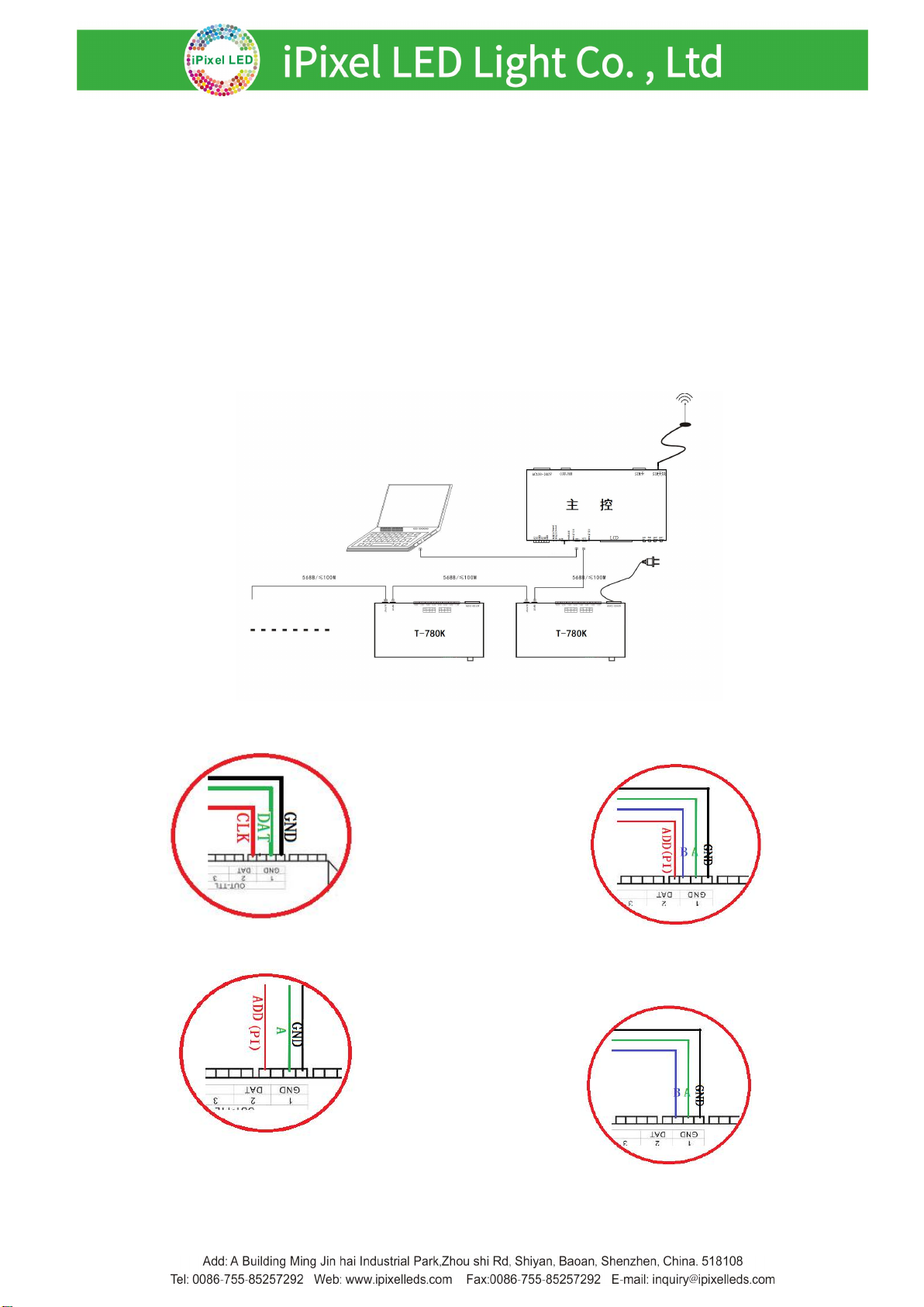
五、Wiring diagram
1、Computer online wiring diagram
2. Offline master control wiring diagram
3. Online and offiline use wiring diagram

6
4. Controller signal output pirt wiring diagram
①. Regular laight wiring diagram ②.DMX512 differential signal wiring diagram
③. DMX512 single signal line wiring diagram ④. DMX512 differential signal wiring diagram
(AB wire to write address)

7
5. Controller--Online mode--Computer IP address setting
1. Turn on the computer --- network and sharing
center;
2. Click to change the adapter settings;
3. ight click on Local Area Connection - Properties;
4. Click on "Internet Protocol Version 4 (TCP/IPV4)";
5. Change IP
IP:192.168.60.2
Subnet mask:255.255.255.0
6. Click OK to complete the IP address setting.
Note: This IP setting is applicable to regular online/Madrix software control.
六、T-780K numbering function operate
T-780K numbering has three methods: Computer number (recommended), master number, and
branch number.
1. Controller (computer software port) numbering
1.1. The computer and the controller are connected by a network cable (using the international
standard TCP/IP network protocol, and the network cable is 568B through)
1.2. Open the software LedPlayer-k and click on "Project Configuration" as shown in Figure 1.
1.3. Click on "Online Code", as shown in Figure 2.
1.4. Set the controller start number, click the online number button, start numbering, as shown in
Figure 3.
Figure 1 Figure 2 Figure 3
1.5. Complete the online code and check the controller number.

8
2. Conttoller(master control operation ) numbering function
The main control and sub-control (T-780K) are connected through the network cable (using the international
standard TCP/IP network protocol, and the network cable is 568B through).
2.1. The master control presses the “SPEED-/speed-” button to power on, and the “MODE” button adjusts the
arrow to “Set Slave ID” as shown in the figure:
2.2. Press the “SET”button again, the main control display enters the numbering page, the “SPEED+”
button and the “SPEED-”button adjust the number of the starting sub-control, as shown below:
2.3. After completing the number setting, press the “SET/Save”button to start the numbering.
2.4.The first step of the controller number is to automatically count the number of sub-controls. The display
"Write OK: 003" (take 3 sub-control numbers as an example)
2.5. The number is completed, the main control display: As shown in the figure "Write Num: 003", 3 controllers
are programmed.
“Last ID: 003” means the last controller number is 3
Sub-control T-780K display as below:

9
First set ID:0001 Second set ID:0002 Third set ID:0003
2.6. Check the controller number. If you need to renumber, press and hold the “SPEED-”button
to restart the numbering. If you do not need to renumber, press any button—the master
restarts and returns to the playback mode.
Note 1: When the controller is numbered, the level network port must be connected in strict accordance with
the controller silkscreen prompt (IN/OUT); the maximum sub-control number is 203. .
3. Controller (T-780K sub-control) numbering
The T-780K and the T-780K use network cable connect (using the international standard TCP/IP network
protocol, the network cable is 568B straight)
3.1. The first T-780K controller, press and hold the “SPEED-”button, the controller will be powered on and
enter the manual coding mode. The display shows: “ID: 0001”as shown in the figure, ie the current
number of the controller is No. 1, press the “SPEED+”and “SPEED-”keys adjust the starting number.
Button silk screen
SET
MENU
SPEED+
SPEED-
Button function
Numbering start button
/
Digital plus
Digital subtraction
NOTE
Numbering mode, "MODE"
button is not available
Press "-" to power on, enter the
numbering mode
3.2. After completing the start number adjustment, press the “SET”button to start the
number start number and display: “Writing...”
3.3. During the numbering process, the controller detects the number of connected
controllers (the number of connected controllers). As shown in Figure 003, a total of
three controllers are detected.
3.4. The number is completed, the first controller displays: as shown in the figure "Write
Num:003": 3 controllelers are searched
" Last ID: 003" The last one is numbered 3

10
Other controller display, as show in the figure:
“ID:0002 A” ;ID:0002 means the controller number is No. 2 A: Indicates that the number
is automatically generated
The second set: A-0002 The third set: A-0003
3.5.Check whether each controller number is correct or needs to be renumbered. Then the first
T-780K controller long time presses the “SPEED-” button to return to the manual numbering;
the end numbering can be exited by pressing the button (any button is ok). The first T-780K
controller restarts “Restart...” and returns to normal play mode.
Note: When the controller is numbered, the cascaded networking ports must be connected in strict accordance
with the controller silkscreen prompt (INPUT/OUTPUT).
七、T-780K parameter setting and function operation
Press the “SET”button, and the controller will start up and enter the parameter
setting and other function interfaces.
①. PLAY Built-in effect playback mode
②. WRITE ADDRESS Address writing mode
③. TEST DMX ADDR Lamps address testing mode
④. RGB,RGBW Lamps channel selection mode
⑤. 100-BASE Transmission rate selection mode
1. Built-in effects mode (support RGB/RGBW these two
kinds channel lamps)
1.1. Press the “SET”button, and the controller will start up, enter the parameter setting and
other function interfaces, as shown in the figure:
Table des matières
Autres manuels iPixel LED Light Contrôleurs