Intech Instruments Ltd Ezeio Manuel utilisateur

1 | Page Ezeio v9 - 120317
Eze Cloud Based Monitoring Systems. Created by Intech Instruments Ltd December 2014
Important Supplementary Manual to the main Ezeio manual.
Index:
Page
2. Section 1: Ezeio Controller input configurations.
3. Ezeio Configuration of the Ezeio Controller inputs.
5. Section 2a: Introducing the 2400 input and output expansion field stations.
6. Configuring the 2400-A16 and connecting to the Ezeio Controller.
7. Setting the 2400-A16 Station number, Polling Address.
8. Configuring the Ezeio with the 2400-A16.
10. 2400-A16 input examples on the Ezeio.
11. Section 2b: Introducing the 2300 input and output expansion field stations.
15. Calibration Offset adjustment during a calibration survey
16. Digital on/off inputs.
17. Alarm options and configuration, including alarm relay outputs, alarm text messages, and
alarm email messages.
19 Activating GSM sims in the ezeio Controller
Ezeio Controller and the 2400-A16 input expansion.
Antennas on GSM model only
GPS (Positioning) Antenna
GSM/3G (communication) antenna

2 | Page Ezeio v9 - 120317
Section 1 covers the Ezeio Controller 4 local inputs, and Section 2 covers adding the
power of the 2400-A16, to expand the inputs up to 40, plus adding more outputs.
Section 1: Configuring the Ezeio Controller local inputs:
The Ezeio™ controller has four standard inputs. Each input may be configured individually in one of the four
ways described here:
To access the input jumper settings, open the Ezeio™ by removing the four black screws.
Read the Ezeio manual pages 12 through to and including 15, covering input connections.
Jumper setting Description
0~5Vdc.
Input impedance is >70kOhm.
Raw reading is about 10000 at 5.0V (0.5V per count).
0~10Vdc.
Input impedance is >70kOhm.
Raw reading is about 10000 at 10.0V (1mV per count).
0~30mA (suitable for 4~20mA transducers).
An internal 100 Ohm resistor connects the input terminal to Common.
Raw reading is about 10000 at 30mA (3uA per count).
Contact, Pulse or Resistive (0~50Ohm).
An Internal 10K resistor will hold the input to 5V.
This is the factory default setting.
4~20mA Resistance or
Pulse input

3 | Page Ezeio v9 - 120317
Getting started with configuration:
Go to www.ezecontrol.com
Click on the ‘Configure’ tag
And then the + by the inputs:
Now select which input you wish to configure. Select the ‘Input Type’ to match the configuration of the
‘Jumper’ setting in the table above. Always remember to select ‘Save Changes’ after making a change.
Important Note: The analogue inputs have a nominal calibration only (ex factory), and where accuracy is
required, individual calibration of each channel is required. This is done with the use of an accurate signal
calibrator.
Follow these easy steps:
1. As an example, on the Ezeio Controller Input 2, the analogue input is set to 0~10v dc. Apply an accurate
10v signal to this input and on the Ezeio ‘Status Page’, note the ‘Raw’ reading on channel 2.
In this example below the Raw reading = 9798.
Enter your Account number, Login and Password.

4 | Page Ezeio v9 - 120317
2. Now go to the Eze Ezeio Configure page and click on ‘Input Type’ and select ‘Custom’ as shown.
3. Now click on ‘Linear Analogue’ and enter the values as shown next:
4. Now click on ‘Save Changes’ and go back to the Ezeio ‘Status’.
Point 1 and Point 2 are what we want this input to read, which in this
example is ‘0~10v’.
Point 1 is the zero point, which is 0 for the Raw Value and 0 for the Value.
Point 2 = 9798 which is the Raw Value from step 1 at 10v dc input, and the
‘Value’ for this example we want to read 10.
If you wish this to actually read another value, for example 100% then
enter 100.
Click on ‘Use’.

5 | Page Ezeio v9 - 120317
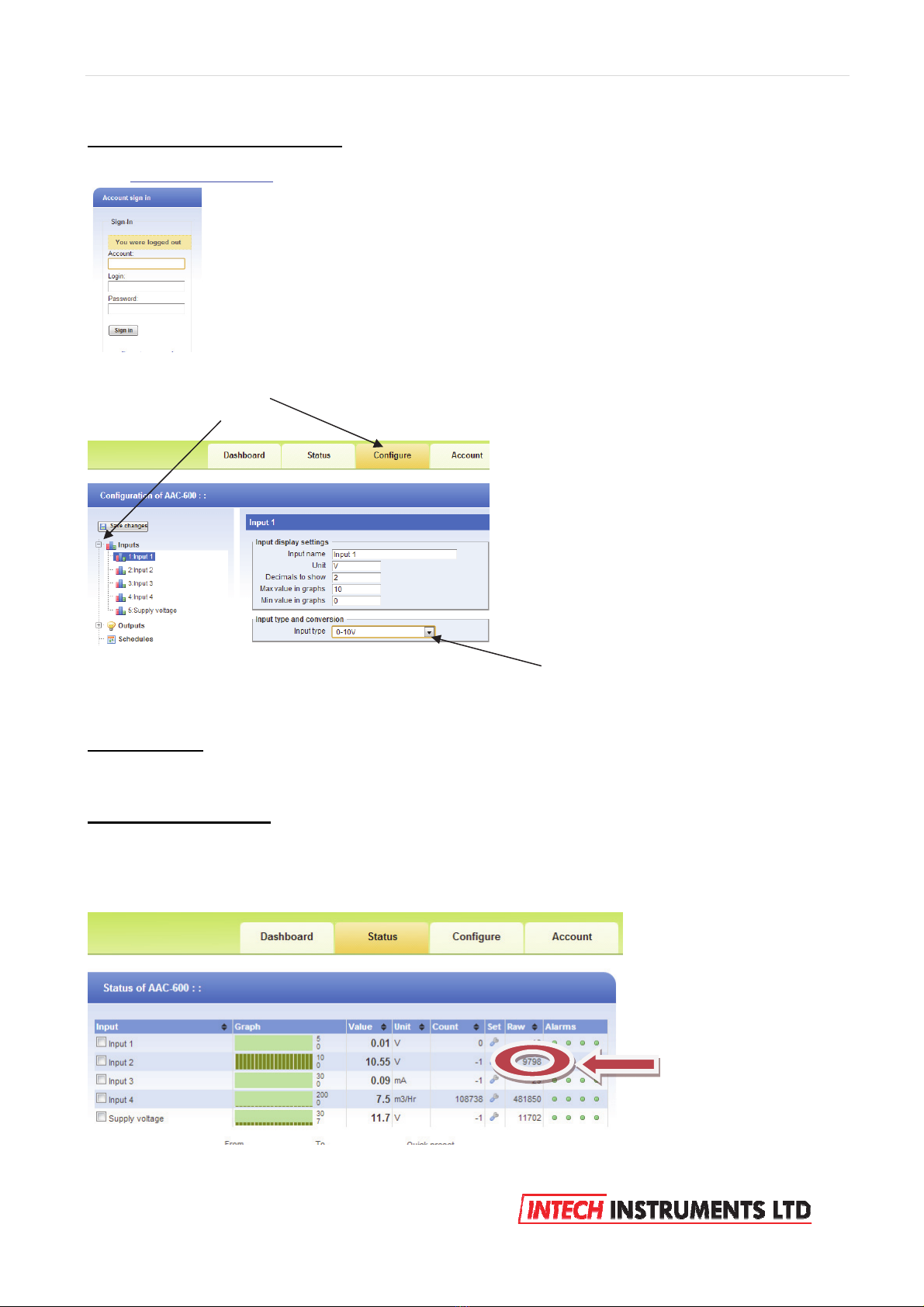
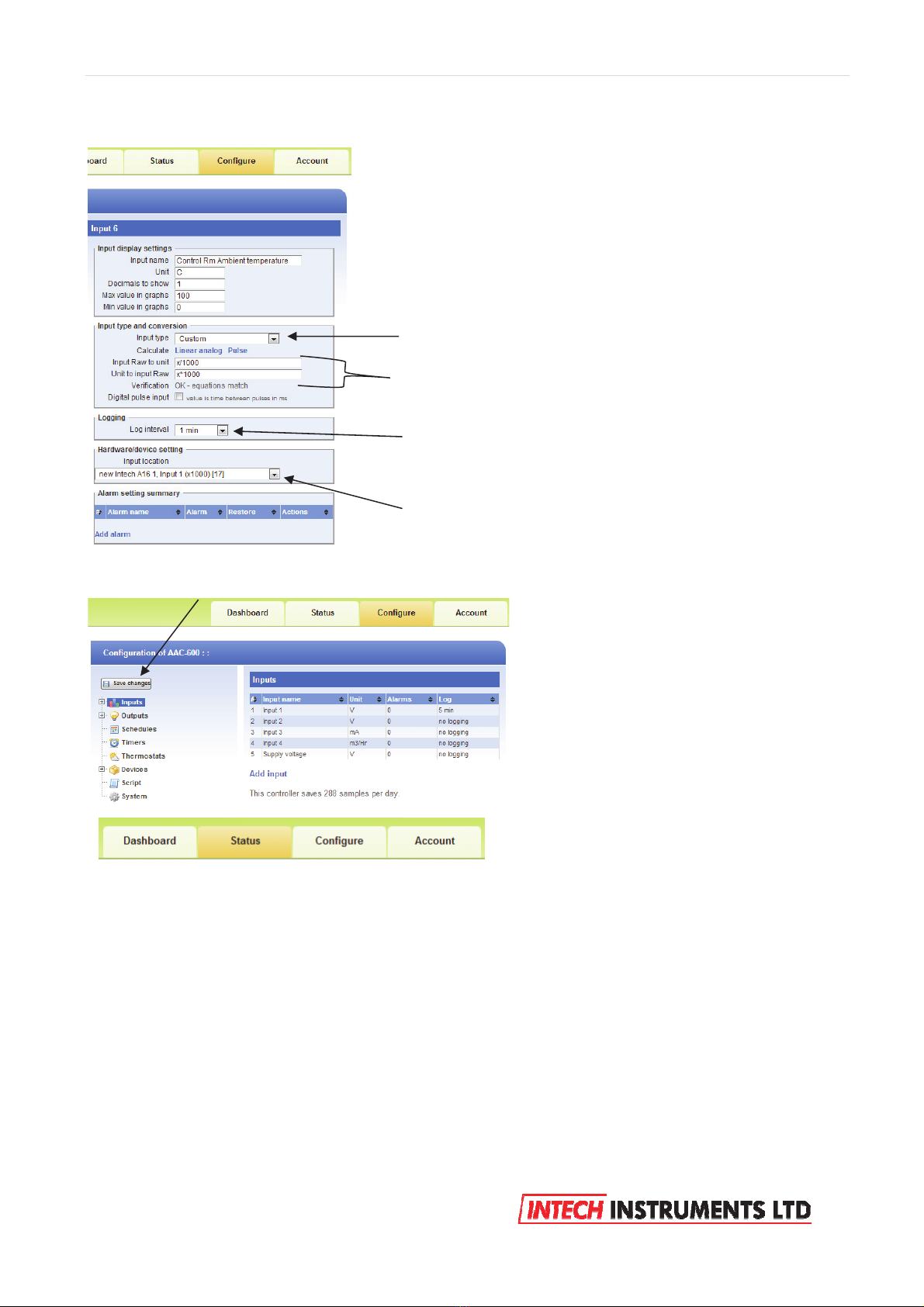
5. The Status screen now displays input 2 at exactly 10.00 (or whatever value you have entered).
6. If you require good accuracy at a particular point of the span, then calibrate at that point instead of the full
span point.
7. Apply this procedure (as applicable) to all other analogue inputs on the Ezeio Controller inputs to achieve
accurate calibration.
Section 2a:
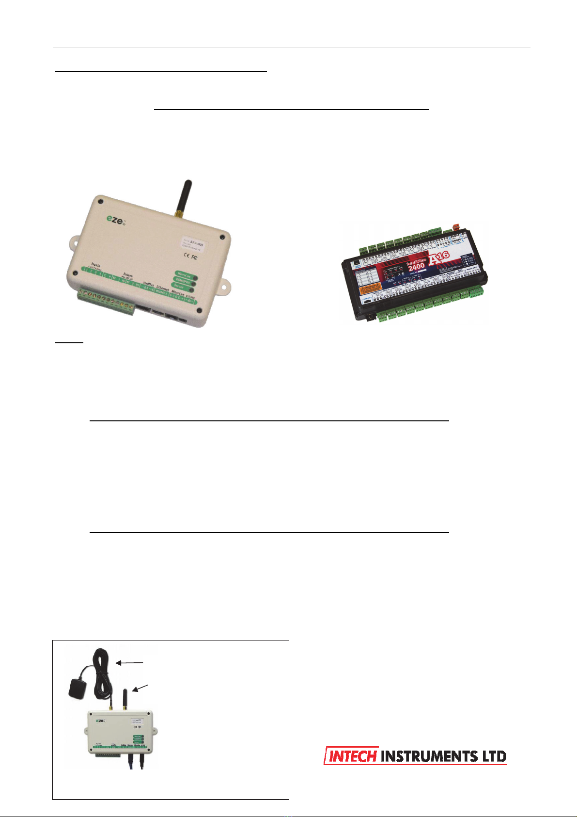
Adding a 2400-A16 station to an Ezeio controller:
The 2400-A16 is a high quality, high accuracy I/O station
(input/output expansion station), designed for a wide variety of
applications, and is easily implemented with the Ezeio.
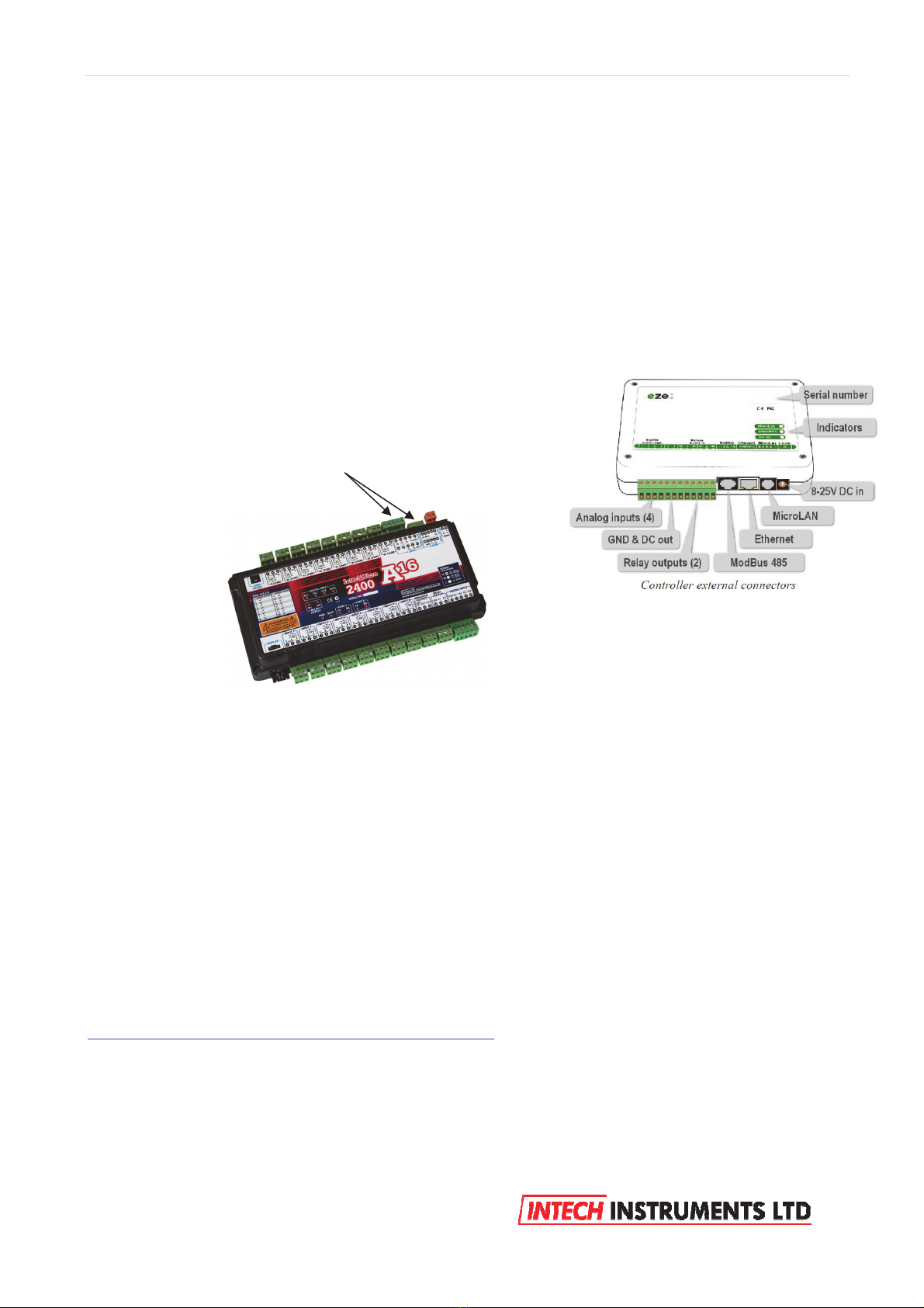
Up to 16 Isolated Universal Analogue Inputs, with Plug In
Terminals.
Each Input is fully Isolated and Individually Selected & Scaled.
RTD, T/C, mA, mV, V & Pulse/Digital as follows:
RTD: Pt100/Pt1000, -200~320°C to -200~800°C.
T/C: B, E, K, J, N, R, S, T, with CJC.
mA: 4~20mA, 0~2.5mA.
mV: -25~25mV to -200~200mV.
V: 0~1V to 0~15V.
Pulse/Digital: Meter pulses, Counting and Frequency.
Max speed 2500Hz.
Four Isolated Digital Inputs.
State or Count.
Max speed 8000Hz.
Two Analogue, Isolated, 4~20mA Outputs.
Two Isolated, Relay Outputs for alarm or control.
Comms Ports:
Port 1: Isolated RS422/RS485 or Ethernet TCP/IP (option).
Port 2: Isolated RS232/RS485.
USB programming port via XU-USB programming key.

6 | Page Ezeio v9 - 120317
Please note: The 2400-A16 I/O expansion station is shortened to ‘A16’ below.
Notes:
a. More than one A16 can be added to an Ezeio controller.
b. The Ezeio Controller will accept up to 40 inputs per Ezeio controller, after which, add another Ezeio.
c. The A16 is available with 3 options for the number of analogue inputs:
8 inputs, 16 inputs.
Follow these steps to add one or more A16’s:
Disconnect both the Ezeio Controller and A16 from the power supply.
First is to connect the A16 to the Ezeio Controller ‘ModBus 485’ port.
The A16 has 2 ports which are both ModBus RTU RS485 capable.
Connection to the Ezeio Controller ‘ModBus 485’ port is by using a standard Ethernet cable plugged into the
Ezeio Controller and broken out to twisted pairs.
Getting started with configeration :
The first task is to configure the A16.
Connect the A16 to a computer as covered bottom page 16 of the ‘2400-A16 Installation Guide’.
If you do not already have a copy of the ‘Intech Micro Station Programmer Software’, download and install
from this link:
http://www.intech.co.nz/downloads/download-software.html
Run the ‘Intech Micro Station Programmer Software’.
Eze Controller
Two of these pairs are used to connect to one of the A16 RS485 ports, to the ‘ModBus 485’
ports of the Ezek Controller as follows:
Blue pair: Blue = 70 on A16 comms.
Blue/White = 71 on A16 comms.
Brown pair: Brown = 74 on A16.
Brown/White = not connected.
After the connections are complete, power up both the Eze Controller and A16.

7 | Page Ezeio v9 - 120317
Click on the ‘Auto Detect 2400 Station’.
Configure the required input channel settings as shown below.
The 2 important areas to make the same as the Ezeio is the Baud rate, the ‘Port Settings’. This A16
configuration screen below displays the parameters the A16 should be set to with special attention to the
‘Address’ which is referred to on the Ezeio Controller as the ‘Polling Address’.
Note that on the A16, the ‘Address number’ can be set differently for each (comms) port, so make sure the
A16 port used for the Ezeio Controller is the same as that used in the Ezeio Controller.
A16 Ezeio
Remember that if two or more A16’s are connected to the Eze
Controller, the A16 ‘Address’ and corresponding Eze ‘Polling Address’
on the 2nd unit must set to a different number. Never use the same
number twice.
For example, the 2nd A16 ‘Address’ and Eze corresponding ‘Polling
Address’ may be set to 2.

8 | Page Ezeio v9 - 120317
Configuring the Ezeio Controller:
Go to www.ezecontrol.com
The first task is to add the A16 onto the Ezeio Controller. Click on the ‘Configure’ option on the tags and wait
for the Configure screen to appear:
Click on ‘Devices’ and then click on ‘Add Device’.
Next, enter the ‘Serial/ModBus Polling Address’, which must be set the same in the A16 as well.
In this example, 1 has been entered and the A16 has been configured as “address 1”:
Enter your Account number, Login and Password.
Scroll down to :
“Intech”
Next select from the list,
either :
“Intech A16”
or
“Intech A16 onboard RE”
The two”Intech A16” options concerns the A16 relay outputs only:
“Intech A16” supports the 2400-R2 (16 Channel Relay Output Expander).
“Intech A16 onboard RE” supports the A16 two onboard relay outputs.
Generally, the most popular option is the “Intech A16 onboard RE”

9 | Page Ezeio v9 - 120317
Next, click on ‘System’.
Next task is to add the A16 inputs onto the Ezeio Controller:
Click on ‘Inputs’ and then click on ‘Add Input’.
Set the Modbus Baud to the same as that
of the A16 (as shown above).
Note: Not all the options are shown.

10 | Page Ezeio v9 - 120317
Example 1: Ezeio temperature input scaling for RTD’s and thermocouples.
Before proceeding any further, Click on ‘Save Changes’.
Select ‘Custom’ for all A16 input configurations.
Type in these 2 calibration details for all listed temperature probes,
both RTD and Thermocouple.
The A16 sends the exact temperature to the Eze Controller.
Chose a ‘Logging’ time.
Note: Failure to select a Logging time will result in this input not
being Viewable on Eze.
In this case, the Ambient Temperature Probe is wired in the A16,
input 1.
Click on ‘Status’ to see the flow meter reading.
Table des matières
Autres manuels Intech Instruments Ltd Instrument de mesure
Manuels Instrument de mesure populaires d'autres marques

Endress+Hauser
Endress+Hauser Proline Promag 50 Caractéristiques techniques

Siemens
Siemens SITRANS F Coriolis FCT030 Manuel de la liste des pièces

KLINGER
KLINGER CMF V Series Manuel utilisateur

EXFO
EXFO FTB-2 Manuel d'exploitation et d'entretien

Keysight
Keysight M8290A Manuel utilisateur

ADTEK
ADTEK MW-5 Manuel utilisateur


