Industrial Labeling Systems Ultimate 3000 Series Manuel
ULTIMATE 3000 Series
Thermal Transfer Printers
Quick Operator’s Guide

The ULTIMATE Printers!
The ULTIMATE Printers!
This manual is intended for all ULT printers in the
ULTIMATE 3000 Series, including the ULT-3320, 3330,
3430, 3460, 3630, 3830
ULTIMATE 3000 Series

EU - Conformity Declaration
We declare herewith that as a result ofthe manner in which the machine designated below was designed,
the type of construction and the machines which, as a result have been brought on to the general market
comply with the relevant fundamental regulations of the EU Rules for Safety and Health. In the event of any
alteration which has not been approved by us being made to any machine as designated below, this
statement shall thereby be made invalid.
Description: Type :
Transfer Printer A-series (A3)
Applied EU Regulations and Norms:
- EC Machinery Regulations 98/37/EU
-Machine Safety EN 292-2:1991
- EC Low Voltage Regulations 73/23/EEC
- Data and Office Machine Safety EN 60950:1992+A1:1993
EN 60950/A2:1993
- EC Electromagnetic Compatibility Regulations 89/336/EEC
- Threshold values for the Interference EN 55022 :1998
of Data Machines
- Limits for harmonic current emission EN 61000-3-2:1995+A1:1998+A2:1998
+A14:1999:2000
- Limits of voltage fluctuation and flicker EN 61000-3-3:1995
- Interference Resistance in both EN 50082-1: 1992-12
Industrial and Small Plants
General Safety Instructions
1. The printer is built exclusively to print die-cut labels, continuous media, and similar
materials !
2. Connect the printer to an outlet with the correct volt age ! The printer is configured for
voltages of 100 to 240 V. Connect only to a power outlet with a grounded contact !
3. The printer must only be connected to devices which have extra low volt age !
4. Power must be OFF before plugging in any accessory, connecting to a computer and
before performing any maintenance on the printer.Also turn the power off on all
appliances before disconnecting from the printer !
5. Do not expose the printer to any moisture, or use in damp or wet areas !
6. The printer will operate with the cover open if necessary. If the printer must be operated
with the cover open, extra care must be taken to avoid allowing hair, jewelry, clothing,
etc. near the moving parts !
7. During the print process the printhead will become hot. Use extra caution when touching
the printhead. Do not touch the printing surface of the printhead with your hand !
8. Before starting any maintenance, power OFF the printer and disconnect the printer from
the outlet !
9. Any adjustments or repairs which are not described in this manual, should only be
carried out by an authorized service technician !
WARNING !
To avoid possible electric shock, do not open the backside cover !
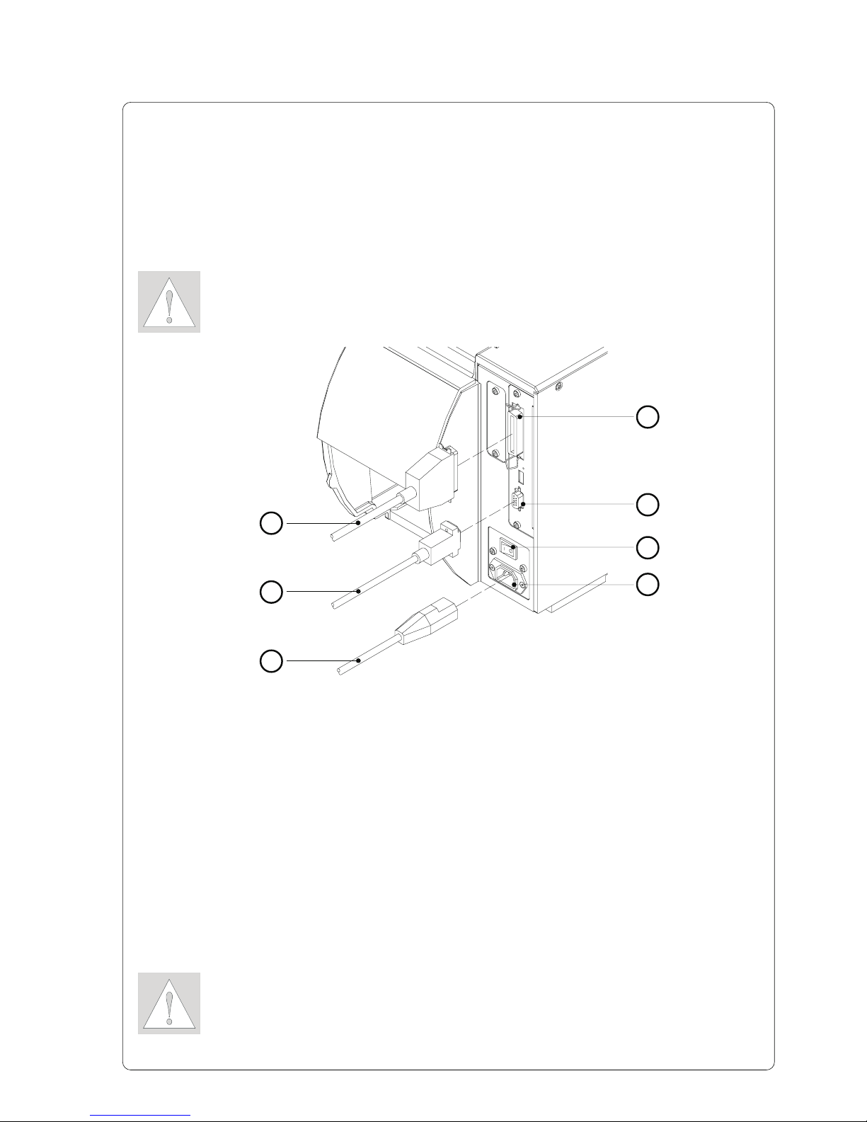
Connecting the Printer
Connection to Power Supply
The printer is equipped with a wide range power unit (100-240V~), so it is
possible to use the printer both with a voltage of 230V~/50 Hz and with a
voltage of 115V~/60 Hz without making changes to the printer.
CAUTION !
Make sure the power switch (6) is in position "
O
" (OFF) before
connecting the printer to a power supply !
Connection to a Computer
As standard, the printer is equipped with a bi-directional parallel interface ( 4)
and a serial RS-232-interface with a 9 pin connector (5).
For serial connection, make sure the serial interface RS-232 of the printer is
correctly configured to the settings of your computer (see Operator's Manual).
Connect the computer and the printer with a suitable cable ( 1,2) and secure the
cable connections with screws provided on the connectors.
CAUTION !
Make sure that all connected computers and their connecting cables are
correctly grounded.
1
2
Figure 1
Insert the power cable (3) supplied in the accessories carton into the power
supply connector (7) and contact the cable to a grounded outlet.
3
4
5
6
7
1
2
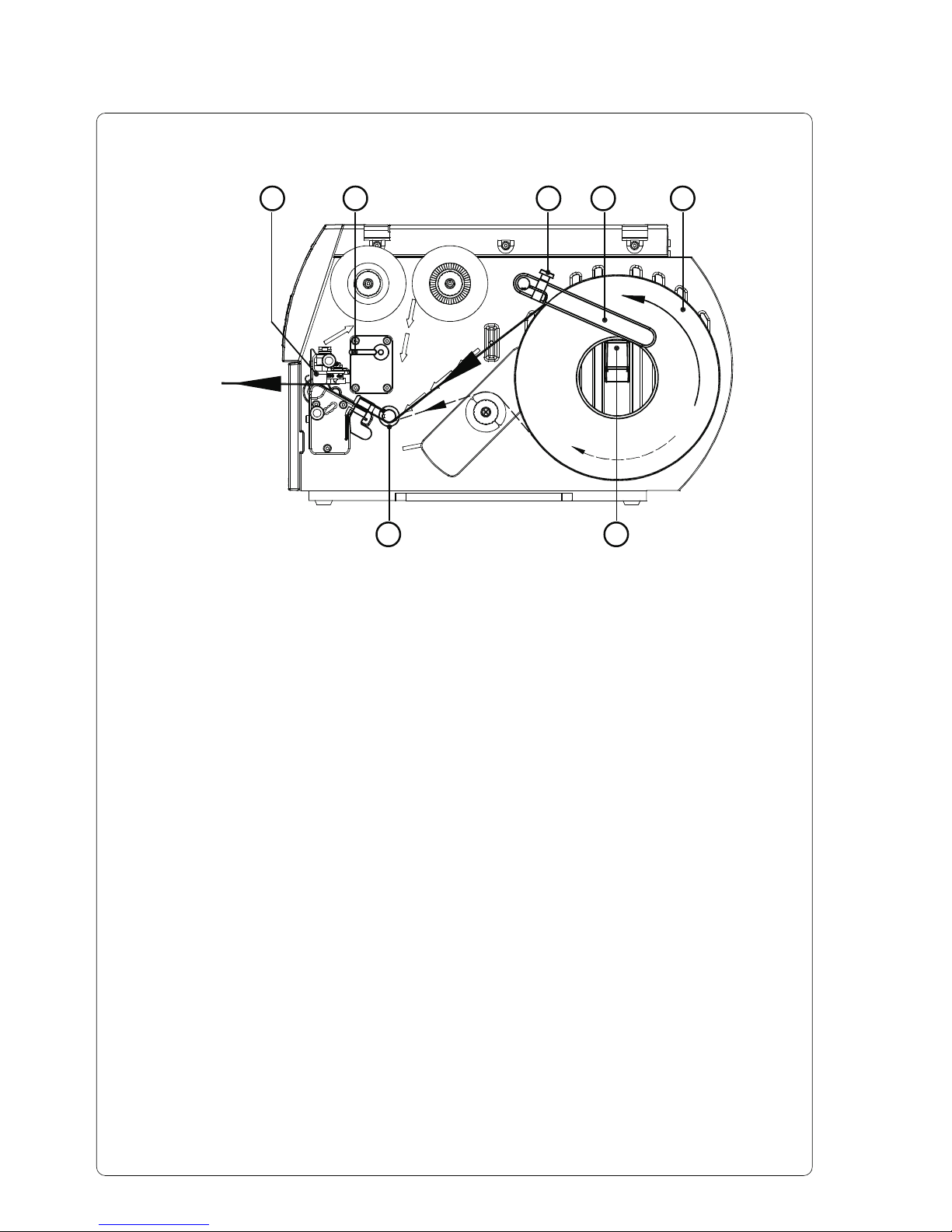
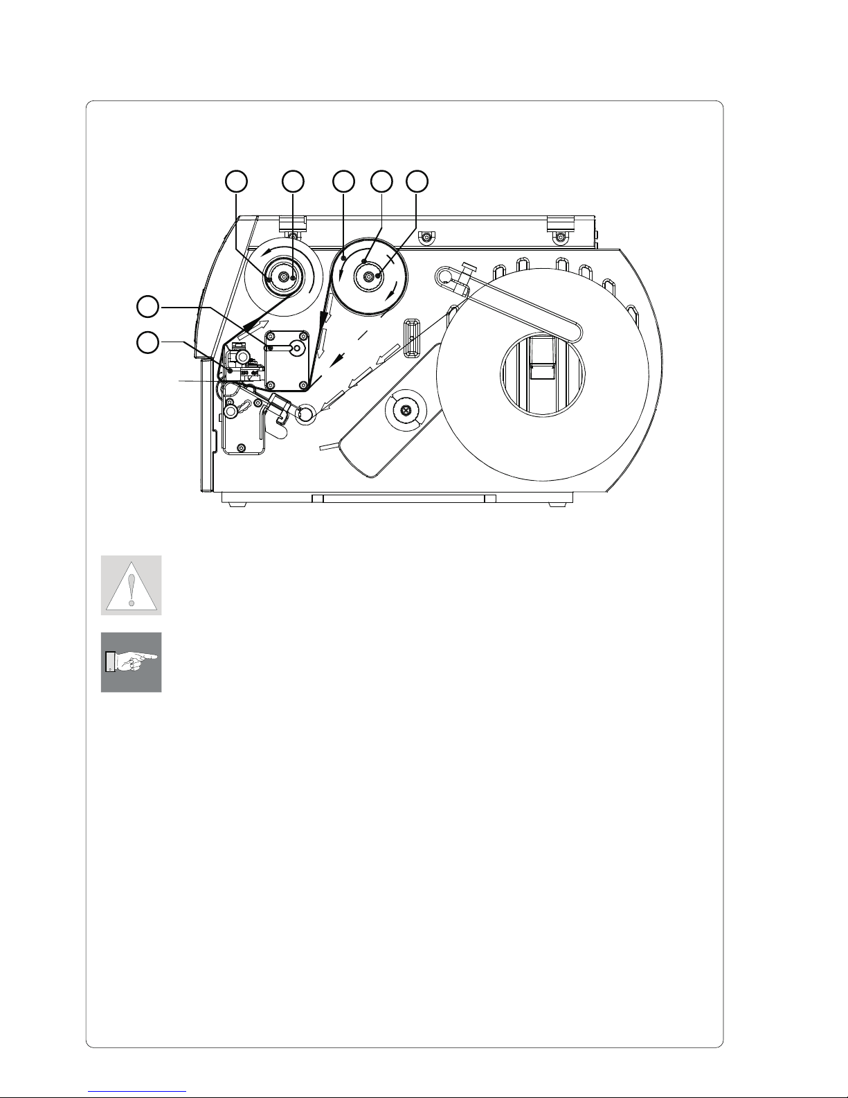
Loading Labels
Figure 2
The following steps are valid for loading labels in tear-off mode.
Instructions for loading labels in rewind or dispense mode and for loading
fanfold labels can be found in the Printer's Operator Manual or in the
documentation of the Present Sensor.
1. Loosen the knurled screw (3), swing the media retainer (4) upwards and
slide it out as far as possible.
2. Place the media roll (5) onto the media hub (6) and unwind a strip of
media from the media roll. Make sure the labels are facing up. Slide the
roll onto the media hub (6) until its stops.
3. Swing the media retainer (4) downwards until it touches the media hub (6).
Push the media retainer against the supply role until it rests against the
label media. Tighten the knurled screw (3).
4. Raise the printhead assembly (1) by rotating the lever (2) clockwise until it
stops.
5. Slide the media guide ring (7) outward, allowing enough clearance for the
label stock's width when loaded.
6. Slide the media strip through the printer as shown in figure 2. The feed
path for labels wound-out is represented by a solid line, and the feed path
for wound-in labels is represented by a broken line.
7. Move the label edge sensor assembly ( 8) in such a position that the
sensor (9) itself can detect label gaps, notches or reflective marks.
The adjustment of the sensor is performed by sliding the handle ( 10) in
and out.
12345
67
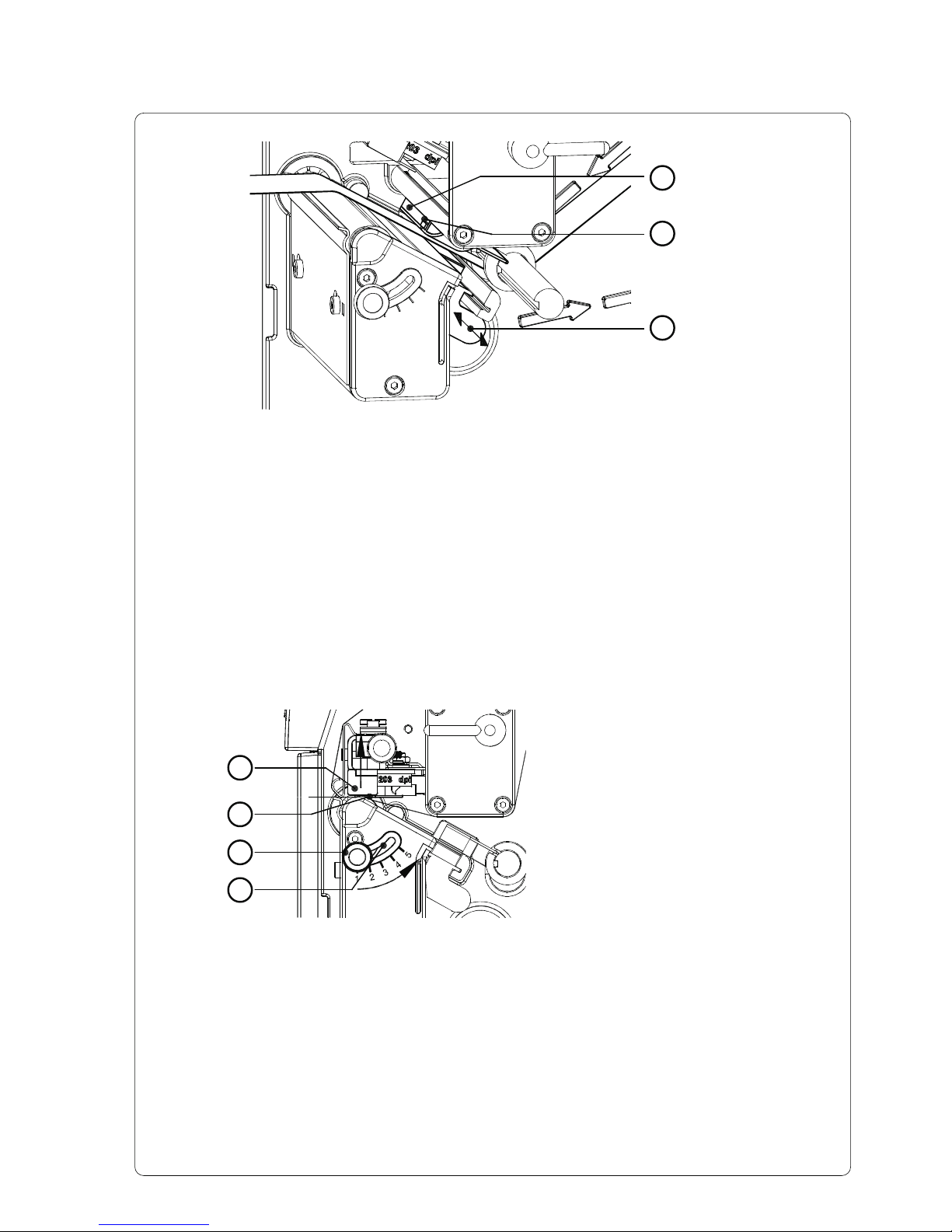
Figure 3
8. Slide the media guide ring (7) inward until it lightly touches the side of the
media strip.
9. Lower the printhead by rotating the lever (2) counter-clockwise until it
locks.
10. When printing narrow label stock, it is necessary to activate the printhead
support.
8
9
10
Adjustment of the Printhead Support
1. The current position of the printhead support (2) is visible at the scale on
the elongated hole (4).
2. For wide media position 1is recommended. In this position the printhead
support (2) is not used.
3. For narrow media, loosen the knurled knob (3) and slide it slowly towards
position 5. The printhead (1) is lifted upward away from the printing roller.
4. Check the adjustment by printing a label to check the print darkness.
5. Once you are satisfied with the printed image, tighten the knurled knob
(3).
Figure 4
1
2
3
4
When printing narrow label stock
(width less than the half of the
maximum print width), it is possible
that the printhead will come into direct
contact with the printing roller in the
area where there is no media. This
could lead to premature failure on the
printhead and can also cause a
variation in the darkness of the print
across the label. This fault can be
corrected by adjusting the printhead
support (2) :
3
4
Loading Transfer Ribbon
CAUTION !
To avoid premature deterioration of the printhead, make sure the transfer
ribbon is slightly wider than the width of label backing.
NOTICE !
For direct thermal printing no transfer ribbon is needed !
1. Raise the printhead assembly (2) by rotating the lever (1) clockwise until it
stops.
2. Slide the roll of transfer ribbon (5) as far as possible onto the ribbon
supply hub (6).
3. Hold tight the supply roll (5) and rotate the knurled knob (7) counter-
clockwise to clamp the roll onto the ribbon supply hub ( 6).
4. Slide a cardboard core (3) onto the ribbon take up hub. Clamp the core by
rotating the knurled knob (4) counter-clockwise.
5. Feed the transfer ribbon along the path as shown in figure 5 and attach it
to the cardboard core (3) using a piece of tape or a label. In figure 5 the
solid line represents ribbon with ink on the inner side, and the broken line
represents ribbon with ink on the outer side.
6. Turn the ribbon take up hub counter-clockwise until the ribbon is taut and
without any wrinkles.
7. Lower the printhead by rotating the lever (1) counter-clockwise until it
locks.
764
2
1
35
Figure 5
5
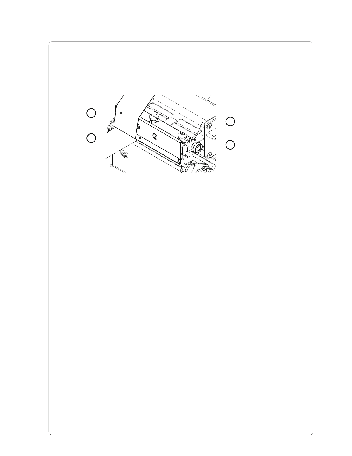
Adjustment of the Transfer Ribbon
In the event that wrinkles appear in the transfer ribbon (1), which cause an
inconsistent print image, the transfer ribbon shield ( 2) can be adjusted to
remove the wrinkles. The adjustment should be done during the printing
process.
1. The current position is visible on the scale ( 3).
2. To change the position, rotate the knurled knob ( 4). Rotating it in the
direction of "+" will tighten the transfer ribbon the inner edge of the transfer
ribbon. Rotating it in the direction of "-" will tighten the outer edge of the
transfer ribbon.
To eliminate the wrinkles, tighten the side where the wrinkles are
originating.
Figure 6
1
2
4
3
6
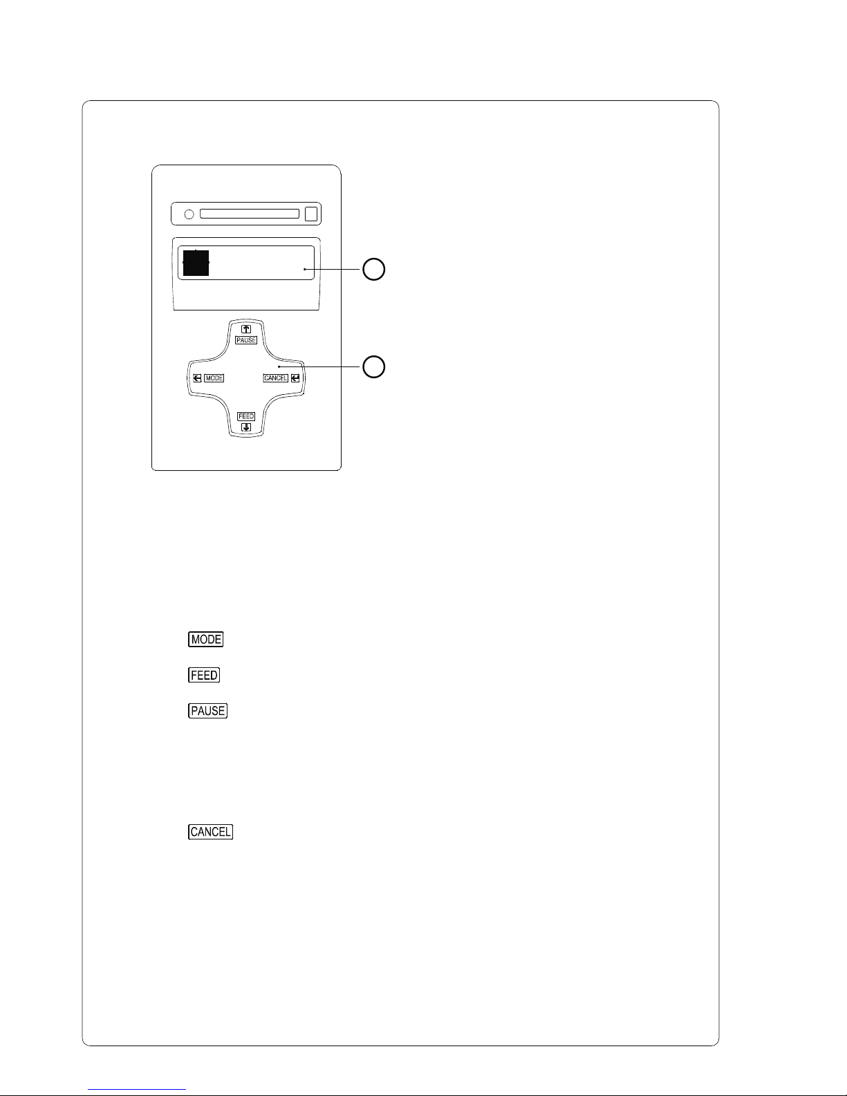
Control Panel
The control panel consists of a
graphic display (1) and the Navigator
Pad (2) with four integrated keys.
The control panel display constantly
provides the operator with realtime
information concerning the current
printer mode and label processing.
The function and operation of the keys
depends on the current mode.
The available functions are marked by
illuminating the valid symbols and text
in the keys.
Key Functions during Printing
Online
2
1
Figure 7
Key Description Function
on - Switches to OFFLINE menue.
on - Performs a label feed.
on - Interrupts the current print job.
on - Continues the interrupted print job.
flashes - Continous current print job after fault correction
(on) - Repeats the print of the last label, after the previous
print job has been completed.
(Only when setup parameter "Pause reprint" is on.)
on - Short press : cancels the current print job
- Long press : cancels the current print job and
deletes all jobs contained in the
internal memory
flashes - Cancels the print job after fault
(on) - Clears internal memory of the previous print job.
"Pause reprint" is no longer available.
Table des matières


