inDESIGN iD-SMA50 Manuel utilisateur

iD-SMA50: INSTALLATION & OPERATION MANUAL
PAGE 2
The inDESIGN iD-SMA50 is an active two-way stereo speaker
system consisting of one powered and one passive speaker.
The speakers are compact, architecturally pleasing and come
supplied with adjustable mounting brackets.
Features include Auto Standby, an on-board 25W stereo
amplier, Treble, Bass and Volume controls as well as
unbalanced stereo RCA and balanced stereo inputs.
The iD-SMA50 features a 5.25” bass driver, a 1” piezo high
frequency tweeter delivering a solid 2 x 25 watts RMS of clear,
intelligible power.
The inDESIGN iD-SMA50 powered speakers deliver a new
standard of high quality sound reinforcement for a variety of
audio and visual applications. Compact and well designed,
they are easy to operate and are set to become the standard
in many AV installations. The speakers are available in white (iD-
SMA50-W) and black (iD-SMA50-B) variants.
INTRODUCTION
INTRODUCTION 2
IMPORTANT SAFETY
INSTRUCTIONS 3
FRONT PANEL 4
REAR PANEL 5
REMOTE CONTROL 6
MOUNTING 7
SPECIFICATIONS 8
PLOT DIAGRAMS 9
WARRANTY INFO 11
CONTENTS
Electrical and Safety Warnings
THESE SERVICE INSTRUCTIONS ARE FOR USE BY QUALIFIED SERVICE PERSONNEL ONLY.
TO REDUCE THE RISK OF ELECTRIC SHOCK DO NOT PERFORM ANY SERVICING
OTHER THAN THAT CONTAINED IN THE OPERATING INSTRUCTIONS
UNLESS YOU ARE QUALIFIED TO DO SO.
CAUTION
The lightening ash with arrowhead
symbol, with an equilateral triangle,
is intended to alert the user to the
presence of un-insulated
“dangerous voltage” within the products
enclosure that may be of sufcient
magnitude to constitute a risk of electric
shock to persons.
WARNING: TO REDUCE THE RISK OF ELECTRIC
SHOCK, DO NOT REMOVE COVER (OR BACK).
NO USER SERVICEABLE PARTS INSIDE. REFER
SERVICING TO QUALIFIED SERVICE PERSONNEL.
WARNING: TO REDUCE THE RISK OF FIRE OR
ELECTRICAL SHOCK, DO NOT EXPOSE THIS
APPLIANCE TO RAIN OR MOISTURE.
The exclamation point within an
equilateral triangle is intended to
alert the user to the presence of
important operating and maintenance
(servicing) instructions in the literature
accompanying the appliance.
iD-SMA50: INSTALLATION & OPERATION MANUAL PAGE 3
IMPORTANT SAFETY INSTRUCTIONS
WARNING: There are no user serviceable parts inside. Refer all servicing to qualied service personnel.
1. Read these instructions.
2. Keep these instructions.
3. Heed all warnings.
4. Follow all instructions.
5. To prevent injury please refer to these instructions for electrical and safety information before installing
or operating the apparatus.
6. No naked ame sources such as lighted candles should be placed on the apparatus.
7. Operation of this apparatus is recommended for moderate climates only.
8. This apparatus must not be exposed to dripping or splashing liquid.
No object lled with liquid, such as a vase, should be placed on the apparatus.
9. Clean only with a dry cloth.
10. Do not block any of the ventilation openings. Install in accordance with the manufacturer’s instructions.
11. Do not install near any heat sources such as radiators, heaters, stoves, or other apparatuses
(including ampliers) that produce heat.
12. Unplug this apparatus during lightening storms or when not in use for long periods of time.
13. Protective Earthing Terminal:
The apparatus should be connected to a mains socket outlet with a protective earthing connection.
14. The mains plug/appliance coupler is used as a disconnect device, the disconnect device shall remain
readily operable.
15. When not in use and during transportation, please take care of the power cord set, for example, tie up
the power cord set with a cable tie/something similar. It should be kept away from sharp edges and
the like that can cause abrasion of the power cord set. When put into use again, check that the power
cord set is not damaged. If any damage is found, have the unit checked by a qualied service person
to replace the power cord set specied by the manufacturer.
16. The terminals marked with symbol of “ “ may be of sufcient magnitude to constitute a risk of
electric shock. The external wiring connected to the terminals requires installation by a qualied service
person or the use of ready-made leads or cords.
17. Only use attachments/accessories specied by the manufacturer.
18. Check speaker line load prior to connecting to amplier using an impedance meter.
19. Refer all servicing to qualied service personnel. Servicing is required if the apparatus has been
damaged in any way, such as power-supply cord or plug breakage, damage due to liquid or objects
falling onto the apparatus, exposure to rain or moisture, or if the apparatus does not operate normally,
or has been dropped.
20. Correct Disposal of this Product:
This marking indicates that this product should not be disposed of with other household wastes. To
prevent possible harm to the environment or human health from uncontrolled waste disposal, recycle
it responsibly to promote the sustainable reuse of material resources. To return your used device, please
use the return and collection systems or contact the retailer where the product was purchased. They
can take this product for environmental-safe recycling.
iD-SMA50: INSTALLATION & OPERATION MANUAL
PAGE 4
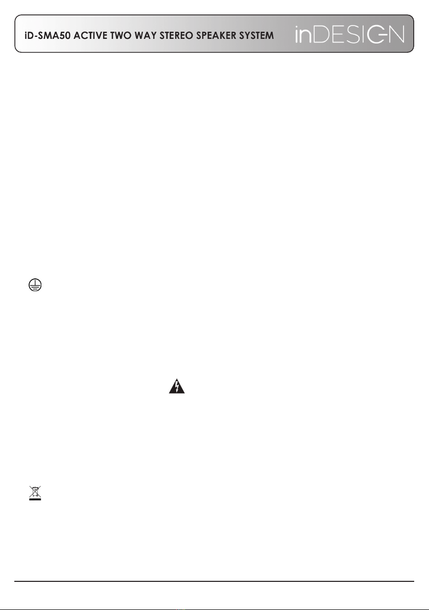
FRONT PANEL – ACTIVE AND PASSIVE
1. 1.0” (25mm) Piezo Tweeter
2. 5.25” (133mm) Bass Driver
3. Status LED
Green LED = Power on
Red LED = Sleep/standby mode
Sleep mode will occur 2:30 mins after no audio signal is present. Introducing audio signal into the
system will bring the system out of sleep mode. Use the included remote control to defeat this feature if
required.
Blinking RED LED = System is muted
This feature is enabled/disabled via the included remote control.
4. Remote control infra-red receiver
1
2
GRILL REMOVED
3 4
iD-SMA50: INSTALLATION & OPERATION MANUAL PAGE 5
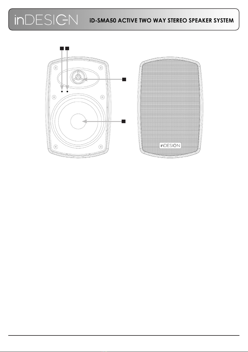
REAR PANEL – ACTIVE AND PASSIVE
1. Volume Control: Provides adjustment of the volume level of the active speaker system. Pressing the Volume knob in will
allow you to choose either unbalanced or balanced inputs
2. Treble: Allows you to adjust the high frequency response of the system.
3. Bass: Allows you to adjust the lower frequency response of the speakers.
4. L/R Inputs: Balanced audio input - Euroblock connectors. Pay particular attend to the polarity of the connections.
5. L/R Inputs: Unbalanced stereo RCA inputs (Left and Right).
6. Power Connection: Insert included main cable into the power socket.
7. Fuse Holder: Always ensue that a 1 A 250vac slow blow fuse is used.
8. Power On/Off Switch: The power switch turns the speaker systems mains supply on and of. When the system is switched
on a Green LED will light on the front panel. When the LED is RED the system is in sleep mode. Sleep mode will occur
2:30mins after no audio signal is present. Introducing audio signal into the system will bring the system out of sleep
mode. A blinking red LED light indicates the system is in mute mode. Use the remote control to un-mute the system.
9. Speaker Output 8 ohm: Connection to the passive 8 Ohm external speaker is provided through a two-pin terminal
socket which comes tted with a removable screw terminal plug. The passive speaker becomes the right whilst the left
channel is the active speaker. Connect the supplied gure-8 or a similar speaker cable between active and passive
speaker. Be sure that the + of the main unit socket is connected to the + (red terminal post) of the passive loudspeaker
and the - of the main unit is connected to the - (black terminal post) of the passive speaker. Never connect the active
Speaker Output terminal to an external speaker that is not the correct 8 Ohm impedance.
10. Passive Speaker Termination: Terminate you speaker cable to the colour coded spring terminals. Take care when
connecting the active speaker to the passive speaker, that both are wired in the same polarity.
Red Terminal = positive (+)
Black Terminal = negative (-)
ACTIVE PASSIVE
1
2
3
4
5
6
7
8
9
10
iD-SMA50: INSTALLATION & OPERATION MANUAL
PAGE 6
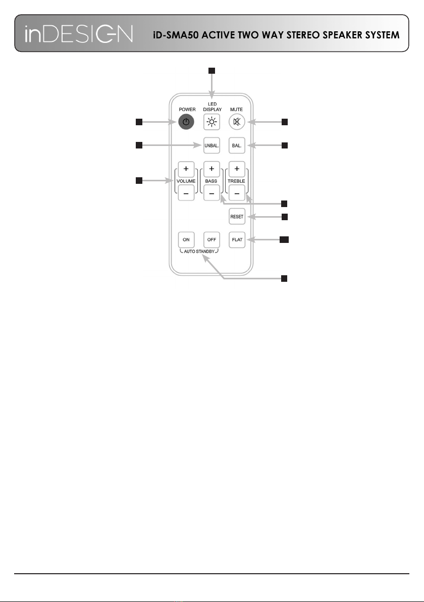
REMOTE CONTROL
1. POWER: on/off. The green LED display lights up when the unit is on. When off, no LED is displayed.
2. LED DISPLAY: turn on/off the LEDs while the unit is operating. When restarting the unit, this function
returns to its default value: LEDs on.
3. MUTE: The red LED blinks on and off when the unit is muted.
4. UN BAL: select the stereo unbalanced RCA input as the audio input source.
5. BAL: select the stereo balanced Euroblock input as the audio input source.
6. VOLUME: increase/decrease the volume in 1 step (range available in 0-36 steps). This only operates
when the unit is on.
7. BASS & TREBLE: increases/decreases by 1 dB (range available of -7 to +7dB) in bass/treble.
8. AUTO STANDBY: keep pressed (for 2 secs.) to activate/deactivate the auto standby function. If this is
activated, after 2’30” with no audio in the inputs and if the remote controlled is not used, the unit will
switch to standby mode.
9. RESET: keep pressed (for 2 secs.) to reset the system to its default values: Sleep/Standby mode ON,
volume= 30 bass; treble = 0.
10. FLAT: keep pressed (for 2 secs.) to reset the system to its default equalizer values: bass= 0; treble= 0.
1
2
3
45
6
9
8
10
7
iD-SMA50: INSTALLATION & OPERATION MANUAL PAGE 7
MOUNTING
When mounting iD-SMA50 speakers the following safety issues must be considered.
The mounting of a permanently installed speaker may be dangerous unless undertaken by a qualied
professional with relevant experience.
Walls and mounting surfaces must be capable of supporting the speaker and bracket in a safe and secure
manner.
All xings must be safely attached to the speaker cabinet and the mounting surface.
All xings must be installed in accordance with the manufacturer’s instructions and specications.
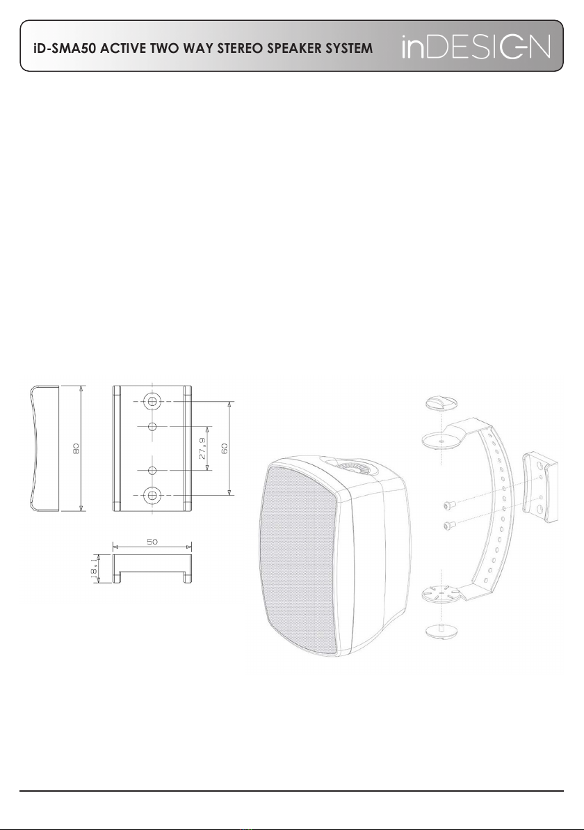
Mounting Brackets
The iD-SMA50 speakers are supplied with vertical wall mount U-brackets. The brackets allow users both pan
and tilt to position the speaker correctly.
Slots for mounting the brackets are spaced 60mm apart. The design of the slots allows for the bracket to
be easily mounted and removed. Simply secure the bracket at the appropriate tilt angle to the wall using
suitable ttings but always ensure that they are t for purpose. Once the bracket is secure, mount the
speaker to the bracket and connect wiring.

iD-SMA50: INSTALLATION & OPERATION MANUAL
PAGE 8
SPECIFICATIONS
SPEAKER SYSTEM 2 WAY ACTIVE SPEAKER, 2 WAY PASSIVE SPEAKER
Power (Continuous) 2x 25 Watts
Auto Standby/Sleep Function YES
Impedance 8 ohm
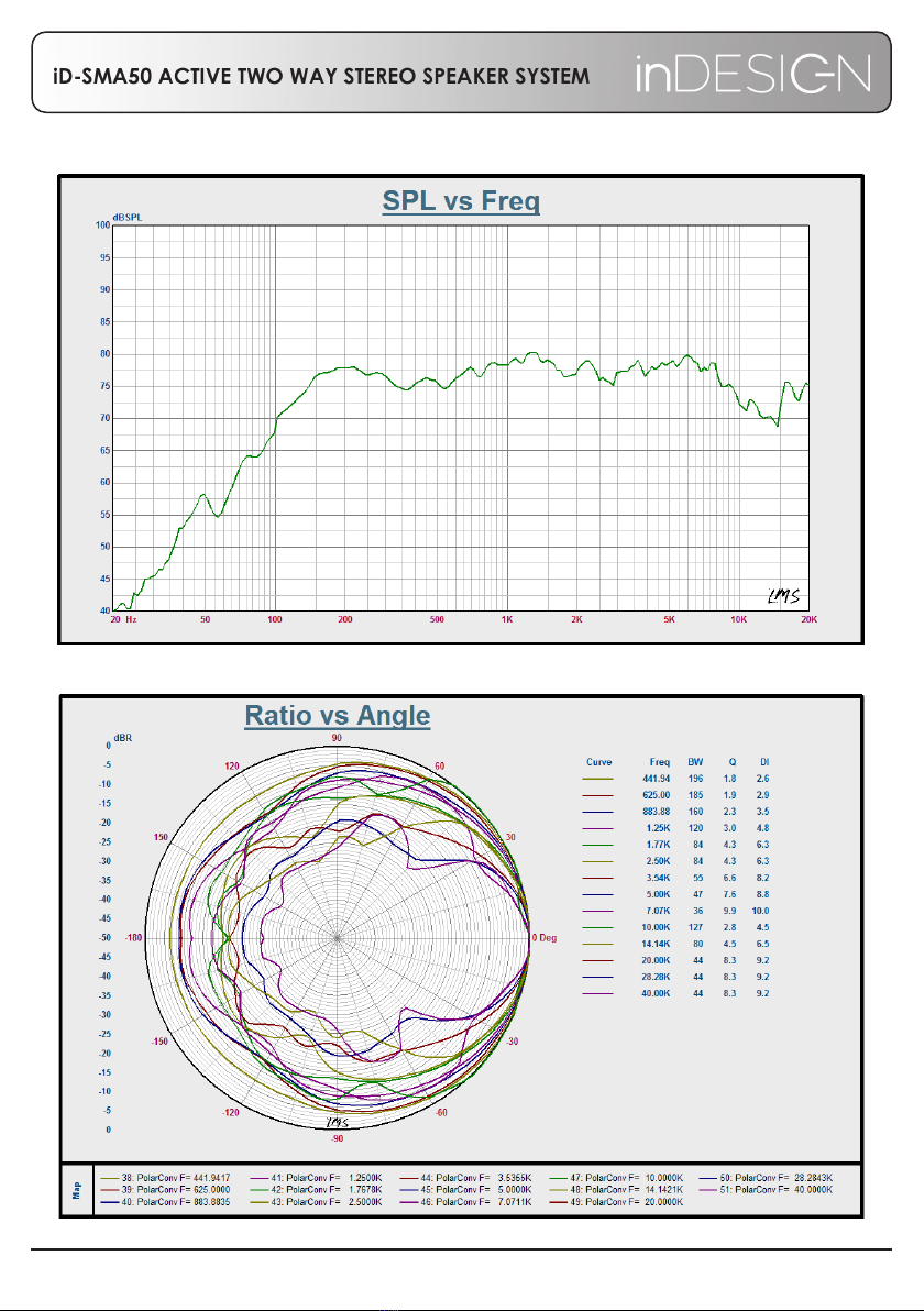
Sensitivity 89dB
Calculated Max. SPL (Per Speaker) l00dB
Frequency Response (-3 dB) 45Hz-20kHz
Frequency Response (-10 dB) 40Hz-22kHz
Speaker Components Woofer: 133mm (5.25” ) Polypropylene
Tweeter: 25mm (1”) Piezo
Dispersion -6dB (H x V) 60 x 90
Mains Power Requirement 230VAC, 50Hz, 50W
Each Speaker Dimension (W x H x D) 163 x 252 x 163 mm (6.5” x 10” x 6.5”)
Box (Pair) Dimensions (W x H x D) 420 x 275 x 195 mm (16.5” x 10.8” x 7.7”)
Weight Active Speaker: 3kg (6.6lbs)
Passive Speaker: 2kg (4.4lbs)
Gross Weight per Pair (Box) 6.8kg (13.4lbs)
Accessories (Supplied) Active Speaker
Passive Speaker
Wall Brackets (Pair)
3 metre Speaker Cable
1.5 metre Main Cord
Instruction Manual
Remote Control!
* Disclaimer: Instructionsandspecicationsarecorrectattimeofprinting.
Informationwithinmaybesubjecttochangewithoutnotice.
iD-SMA50: INSTALLATION & OPERATION MANUAL PAGE 9

iD-SMA50: INSTALLATION & OPERATION MANUAL
PAGE 10
NOTES
Table des matières
Autres manuels inDESIGN Intervenants


Manuels Intervenants populaires d'autres marques


Bowers & Wilkins
Bowers & Wilkins 4 Manuel utilisateur

Sonance
Sonance SONOS OUTDOOR Series Manuel utilisateur

Electro-Voice
Electro-Voice EVID FM4.2 Manuel utilisateur

Pioneer
Pioneer XW-HTD630 Manuel utilisateur

Onn
Onn BWA16AA002 Manuel utilisateur

HP
HP GL313AA - USB Speakers PC Multimedia Manuel utilisateur