INCOE MICROCOM Manuel utilisateur

Instruction Manual
MICROCOM®
ITemperature Controller

MICROCOM®TEMPERATURE CONTROLLER
INSTRUCTION MANUAL
Pg.
www.incoe.com
1 INTRODUCTION
1.1 Main Function Pg. 2
1.2 Controller Specifications Pg. 2
1.3 Technical Features Pg. 2
1.3.1 Temperature Measurement Pg. 2
1.3.2 Temperature Control Pg. 2
1.3.3 Power Output Pg. 3
1.3.4 Other Functions Pg. 3
2 OPERATION
2.1 Requirements for Installation and Operation Pg. 4
2.2 Safety Requirements Pg. 4
2.3 Instructions for Installation Pg. 4
2.4 Initial Start Up Pg. 4
2.5 Controller Operating Mode Pg. 5
2.5.1 Description Pg. 5
2.5.2 Standby Display Pg. 5
2.5.3 “Click & Rotate” Switch Operating Mode Pg. 5
2.5.4 “Click & Rotate” Switch Locking Procedure Pg. 6
2.5.5 Alarms Description Pg. 6
2.5.6 Operator Interface Menu Pg. 6
2.6 Main Menu Pg. 7
2.6.1 Configuration Menu 1 Pg. 8
2.6.2 Configuration Menu 2 Pg. 9
3 TROUBLE SHOOTING
3.1 Trouble Shooting Pg. 11
3.1.1 Faults Table Pg. 11
4 WIRING SCHEMATICS & PLUG DIAGRAMS
4.1 Diagram Label Pg. 12
4.2 1 & 2 Zone Enclosures Pg. 12
4.3 4 Zone Enclosures Utilizing 1614-BRA Pg. 13
4.4 6 Zone/8 Zone Enclosures Utilizing 3214-BRA Pg. 14
4.5 12 Zone Enclosures Utilizing 4814-BRA Pg. 15
5 WARRANTY
5.1 General Terms & Conditions of Sale Pg. 16
6 CONTACT
6.1 Global Service Contacts Pg. 18
6.2 Global Offices Pg. 19
TABLE OF CONTENTS
1
©INCOE®CORPORATION 3/2011

MICROCOM®TEMPERATURE CONTROLLER
INSTRUCTION MANUAL
©INCOE®CORPORATION 4/2010
Pg. www.incoe.com
1.1 MAIN FUNCTION:
The MICROCOM®temperature controller is
designed to control hot runner systems.
1.2 CONTROLLER SPECIFICATIONS:
• INPUT POWER: 230 VAC single phase.
• INPUT POWER RANGE: 207 VAC to 253 VAC.
• MAXIMUM OUTPUT POWER: 3600W.
(15 Amps).
• FREQUENCY: 60Hz / 50Hz.
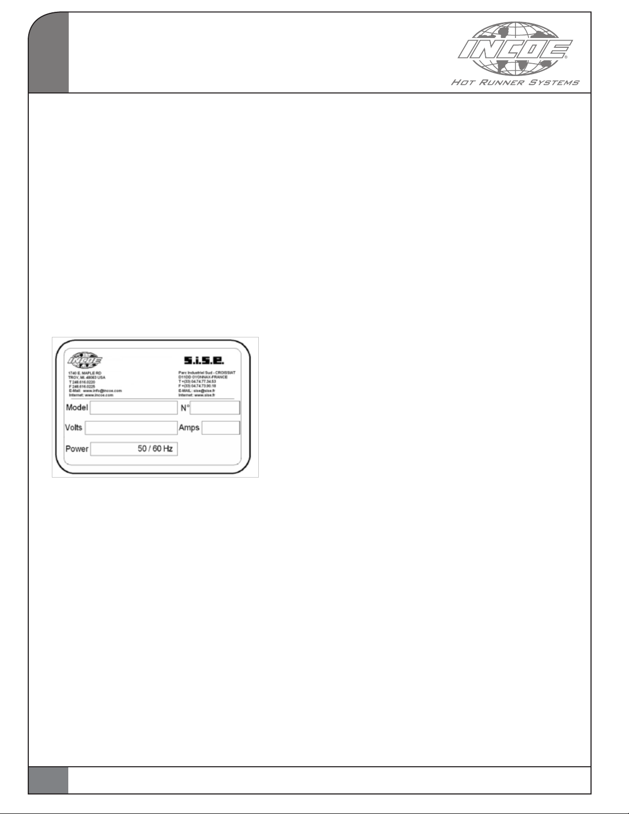
A label is afxed to the cabinet indicating:
1.3 TECHNICAL FEATURES:
1.3.1 TEMPERATURE MEASUREMENT:
• Thermocouple type J (“J” display) or type K
(“nI” display), grounded or ungrounded, with
automatic cold junction compensation
(selection of the thermocouple in the
configuration menu).
• Sampling rate, 83 ms @ 60 Hz or 10 ms @ 50Hz.
• Accuracy +/- 0.5% over the range 32 to 932 °F
(0 - 500°C).
• °F or °C scale (user select in the
configuration menu).
• Reversed thermocouple detection (no power to
the heater, 0% output).
• Broken Thermocouple detection automatically
switches to manual mode by applying the
last stored percentage of power to the heater
(adjustable through software).
• High and Low alarm.
1.3.2 TEMPERATURE CONTROL:
There are 2 control modes :
AUTOMATIC MODE (closed loop):
This is a self-tuning PID control unit. The controller
continuously monitors the behavior of the heater
which it is connected to. The controller adapts its
output to the heater by automatically defining the
P.ID. parameters.
MANUAL MODE (open loop):
In this mode, the controller sends the percentage
of power stored in memory to the manual set
point (default value: 20%). Note that this value can
only be modied in the standby display. When
the controller is in MANUAL mode, high and low
alarms are no longer active. The same is true for
the SoftStart function.
START UP PHASE (“SoftStart phase”):
This phase is designed to avoid cold start failures
and extend the life of the heating element(s). It
eliminates the thermal shock during the transition
from cold to hot.
This phase also removes any moisture that
may have collected in the heating element(s)
by applying low power to the heater or by
progressively increasing power to the heater.
There are 2 types of “SoftStart phases”.
• RAMP DURATION: Heating with maximum
power limited to15% for a 5-minute period or
up to a maximum temperature of 212°F (100°C).
• RAMP RATE: Applying a temperature rate
expressed in °F / min ° (or °C / min ) up to the
user setpoint.
1INTRODUCTION
2

MICROCOM®TEMPERATURE CONTROLLER
INSTRUCTION MANUAL
Pg.
www.incoe.com ©INCOE®CORPORATION 4/2010
Both ramp types can be activated to the
following conditions:
• If the unit is in automatic mode during the
start-up sequence.
• If the unit switches from manual to
automatic mode.
1.3.3 POWER OUTPUT:
• Power output via 15 amp TRIAC (BTA24 800V).
• Double protection of the load via fuse
(Ref : FA15 or ABC-15).
• Protection against over voltages (overvoltage
switch calibrated to 275V).
• Phase angle or zero crossing mode (User
selectable in configuration mode). This
choice is only valid during the control phase.
During SoftStart, the controller remains in
“phase angle” mode for whichever power
mode is selected.
• Accuracy: +/- 1% of nominal.
• Load security : Cut-off with software-driven
relay. The relay cuts off the power to the heater
under the following conditions :
• Controller is powered down by pushing the
ON/OFF switch.
• Anti-Arcing system.
• TRIAC short circuit detection.
• Load or heater detection.
• Load or heater detection: automatic
detection by current measurement: detection
is determined by the following condition:
If measured current is 0 and system call
is positive. The controller then displays the
message “Otr” (As open TRIAC or heater).
• Shorted TRIAC automatic detection: detection
is determined by the following condition: If
measured current is not 0 and if there is no
system call (% power = 0). The controller then
displays the message “Str” (as Shorted TRIAC).
• Automatic detection of load power variation:
After a stabilization period of 120 seconds at
the set temperature, the system computes and
saves the value of the heater (In Watts). The
controller generates an alarm (message “Hra”:
Heater alarm) if there is a variation of at least
20% from the saved value.
1.3.4 OTHER FUNCTIONS :
• Voltage correction (INCOE® Patent 6,107,610):
the system uses a second closed loop control,
which maintains the power applied to the
heater if there is a line voltage variation. The
system is active for voltages as low as 190 VAC.
• Anti arc pin detection: The controller can
automatically detect the presence of an
“Anti arc” pin on enclosure’s edge connector.
When this pin is detected, the system is active
and this allows to cut the gate to the TRIAC, as
well as the safety relay, when the controller is
removed from the enclosure. The response
time for this is less than 20 µsec. If no pin is
detected, the system is simply not active.
1
INTRODUCTION
3

MICROCOM®TEMPERATURE CONTROLLER
INSTRUCTION MANUAL
©INCOE®CORPORATION 4/2010
Pg. www.incoe.com
• The controller type (World).
• The thermocouple type and
the temperature unit
(F or C) used.
• The plant facility’s power
supply frequency and the
detection of the anti-arcing
function (anti-arcing system
detected, anti-arcing system
undetected not detected).
• The version of the
installed software.
• To Switch on the controller (keep the rotary
knob pressed for 3 seconds).
• If the controller displays , this
means either the thermocouple is broken
or is incorrectly wired. In this case, the
controller does not apply any voltage to the
heater (Except if “otc” parameter is set at
“ON”). The problem needs to be corrected
before continuing.
• If the controller displays , it means
the thermocouple is reversed. In this case, the
controller does not apply any voltage to the
heater. The problem needs to be corrected
before continuing.
• If temperature when starting is below 212°F or
100°C, the SoftStart is activated.
In case of problems during start up, refer to the
chapter “Instructions for maintenance”.
2.1 REQUIREMENTS FOR INSTALLING
AND USING:
The control module is designed to operate in a dry
industrial environment.
Operating Temperature range : from 14°F to +158°
or -10°C to +70°C.
2.2 SAFETY REQUIREMENTS:
The controller is protected by :
• Fuses protect TRIAC against over current draw.
• Overvoltage safety feature for protection of
the controller if in put voltage supply
exceeds 275 V.
• Safety relay designed for protection of the
heating element.
2.3 INSTRUCTIONS FOR INSTALLATION:
The controller can be installed in industry standard
enclosures or cabinets. Before installing the
control module make certain the module will fit
into the cabinet. If there are any questions please
contact INCOE®.
2.4 INITIAL START UP
• Install the controller(s) in the appropriate
enclosure or cabinet.
• Connect the cabinet’s power input cable to the
facilities power supply.
• Check all wiring to and from the cabinet.
• Once connected to the plant power supply,
turn on the cabinet using the circuit breaker
on the cabinet.
• At start-up , the display will indicate its status
by the display shown here:
2OPERATION
4

MICROCOM®TEMPERATURE CONTROLLER
INSTRUCTION MANUAL
Pg.
www.incoe.com ©INCOE®CORPORATION 4/2010
2.5 CONTROLLER OPERATING MODE:
2.5.1 DESCRIPTION:
This controller consists of the following:
A “CLICK & ROTATE” switch for data entry
and viewing.
2 sets of 3 digits displays (7 segments + DP),
the upper display is red (it is used for displaying
temperatures, alarms and screen parameters), the
lower display is green (it is used for displaying
the temperature setpoint and the various other
parameter values).
3 LED signals :
#1 : Auto/Manual, when lit controller is in
Manual mode.
#2 : heating rate indicator (percentage of
power display).
#3 : SoftStart Mode.
Upper digits
Lower digits
2.5.2 STANDBY DISPLAY:
In normal operating mode, the upper digits display
the temperature whereas the lower ones display
the setpoint.
If an alarm or a fault, occurs it will be displayed on
the upper digits.
The “On / Off” and “Increase / Decrease”
functions are the only ones operational in the
standby screen display.
The 3 indicators (LED) will only be displayed on the
upper display .
2.5.3 “CLICK & ROTATE” SWITCH
OPERATING MODE:
A single switch is used for performing various
tasks, This switch possesses several functions as
outlined below.:
• 3 second button push = Switches the
controller ON / OFF.
• 5 second button push to unlock if in Lock mode.
• A Double-click allows entry to or to exit
from menu.
i.e. From Stand-By display : a double click
enters in to Main menu, and another double
click exits the Main menu.
• 2 second button push = allows the selection
of a parameter (Parameter is blinking) and the
modification of it.
• If a parameter has been modied, another 2
second push is required to save value.
• Increase / Decrease (Turn right or left) = modify
the parameters and to navigate through the
different menus.
• The standby display becomes active again if
the “Click & Rotate” switch remains untouched
for 5 seconds.
#1 #2 #3
2
OPERATION
5

MICROCOM®TEMPERATURE CONTROLLER
INSTRUCTION MANUAL
©INCOE®CORPORATION 4/2010
Pg. www.incoe.com
2.5.4 “CLICK & ROTATE” SWITCH
LOCKING PROCEDURE:
If the LOC parameter is set to ON (in the
configuration 2 menu), the switch is then
automatically locked after 30 seconds if inactive.
To temporarily unlock the switch, depress the
knob for 5 seconds.
If the button is locked and depressed, then a
“LOC” message will be displayed.
2.5.5 ALARM DESCRIPTIONS:
Alarms and faults only show in the standby
Display, either in a fixed or blinking manner with
the temperature value, as outlined below:
Open thermocouple fault:
• Continuous display of this
fault in the standby display.
Reversed thermocouple fault:
• Continuous display of this
fault in the standby display.
Disconnected heating element fault:
• This fault displays alternately
with temperature. An open
heater is automatically
detected by current
measurement. If the measured
current is 0 and if the
percentage of power is greater
than 0, then this is detected as
a load (heater) fault.
Shorted TRIAC fault:
• This fault displays alternately
with temperature. A shorted
TRIAC is automatically
detected if the measured
current differs from 0 and if
the percentage of power =0.
Heating element load resistance fault:
• This fault displays alternately with
temperature. Automatic detection
of load nominal power variation.
after a 120 second stabilization
period of the temperature
control (temperature +/- 3 °F / °C
of setpoint), the system keeps
the nominal power in memory
and activates an alarm if there
is a variation of at least –20% with
respect to this nominal power.
Temperature high alarm:
• This fault displays alternately
with temperature. It displays
when temperature is higher
than the setpoint + parameter
High alarm value, adjustable in
configuration 1.
Temperature low alarm:
• This fault displays alternately
with temperature. It displays
when temperature is less than
the setpoint parameters Low
alarm value, adjustable in
configuration 1.
2.5.6 OPERATOR INTERFACE MENU:
General View of Menu organization.
Main Menu (Double Click to enter or Exit).
Control mode selection
Display Percentage of
applied power
Display Installed heater power
Display Current measurement
Configuration menu selection
(Push 2 seconds to modify,
Rotate to select 1 or 2, Push 2
seconds again to confirm).
Rotate
2OPERATION
6

MICROCOM®TEMPERATURE CONTROLLER
INSTRUCTION MANUAL
Pg.
www.incoe.com ©INCOE®CORPORATION 4/2010
CFG 1 Menu (Double click to Exit).
High Alarm user select
Low Alarm user select
Maximum Setpoint user select
Minimum Setpoint user select
Time ramp user select
Ramp rate user select
CFG 2 Menu (Double click to Exit).
Temperature units selection
Thermocouple type selection
Output type selection
Operating mode if
thermocouple fault
Initialization of
controller parameters
Controller locking enabled
Controller state on
re-start selection
2.6 MAIN MENU:
The main menu is as follows :
Control mode selection AUTO or MANUAL
(AUTO by default):
Navigation via “Click & Rotate” switch:
If “Increase” display
If “Decrease” display
If “Selected” (Push 2 seconds):
It is possible to modify the
parameter value and choose
AUTO or MANUAL.
Confirm choice by pressing
again for 2 seconds.
Display of the percentage of power applied
to load (Heater) :
In manual mode, the value in the display
corresponds to the manual output setting.
Navigation via “Click & Rotate” switch:
If “Increase” display
If “Decrease” display
If “Selected” (Push 2 seconds):
no effect. Value in %.
Installed power display :
Navigation via “Click & Rotate” switch:
If “Increase” display
If “Decrease” display
If “Selected” (Push 2 seconds):
no effect. Value in Watts.
Current measurement display :
Navigation via “Click & Rotate” switch:
If “Increase” display
If “Decrease” display
If “Selected” (Push 2 seconds):
no effect. Value shown in Amps.
Configuration menu selection:
Selecting parameters in the configuration
menu ( if the configuration entered does
not correspond to any menu, then nothing
happens when validating).
Navigation via “Click & Rotate” switch:
If “Increase” display
If “Decrease” display
If “Selected” (Push 2
seconds): It is possible to
modify the parameter value
and choose 1 or 2.
Confirm choice by pressing
again for 2 seconds.
2
OPERATION
7
Rotate
Rotate

MICROCOM®TEMPERATURE CONTROLLER
INSTRUCTION MANUAL
©INCOE®CORPORATION 4/2010
Pg. www.incoe.com
2.6.1 CONFIGURATION 1 MENU:
The conguration 1 menu is as follows :
High Alarm User Select :
Adjustable parameter setting allows for the
number of degrees above the setpoint to be set
(Default value: 5°F).
Navigation via “Click & Rotate” switch:
If “Increase” display
If “Decrease” display
If “Selected” (Push 2
seconds): It is possible to
modify the parameter value.
Value in °F / °C.
Low alarm:
Adjustable parameter setting allows for the
number of degrees below the setpoint to be set
( Default value: 5°F/C° ).
Navigation via “Click & Rotate” switch:
If “Increase” display
If “Decrease: display
If “Selected” (Push 2 seconds):
It is possible to modify the
parameter value. Value in °F /° C.
Maximum setpoint User Select :
Adjustable parameter to limit the setpoint value to
a maximum value (by default 500°C).
Navigation via “Click & Rotate” switch:
If “Increase”display
If “Decrease”display
If “Selected” (Push 2
seconds): It is possible to
modify the parameter value.
Value in °F or in °C.
Minimum setpoint :
Adjustable parameter to limit the setpoint to a
minimum value (by default 0°C).
Navigation via “Click & Rotate” switch:
If “Increase”display
If “Decrease”display
If “Selected” (Push 2 seconds):
It is possible to modify the
parameter value. Value shown
in °F or in °C.
Time Ramp:
Adjustable parameter, which allows the user to
define the Time Ramp for the SoftStart function.
This ramp is active if the temperature,
when starting up is less than 212°F (100°C).
Controller will heat at 15 percent for duration
adjustable by the operator (from 0 to 99 min)
(Default setting: 5 min).
This duration is stored in memory and will be
used for every new ramp. NOTE: The Time Ramp
cannot be modified nor cancelled while operating.
Navigation via “Click & Rotate” switch:
If “Increase” display
If “Decrease” display
If “Selected” (Push 2
seconds): It is possible to
modify the parameter value.
Value shown in minutes.
Ramp Rate :
Adjustable parameter defining the second mode
of the SoftStart function.
This mode is active if the parameter value differs
from 0. This parameter is the Ramp Rate ( Default
setting: 0°F or °C /min).
Every minute, temperature is increased by a
certain amount of degrees (0 to 99 °F/min or
°C/min), and the percentage of nominal power
is not limited.
2OPERATION
8

MICROCOM®TEMPERATURE CONTROLLER
INSTRUCTION MANUAL
Pg.
www.incoe.com ©INCOE®CORPORATION 4/2010
When temperature reaches setpoint, the ramp is
complete. Its duration depends on the variation
between setpoint and temperature and on the
increase per minute selected.
While the ramp is operating, it is possible
to modify the setpoint, which allows for
adjustments whether the temperature is below or
above the setpoint.
Example :
Initial temperature is 70°F, setpoint is 430°F, Rate
Ramp is 60°F/min.
The ramp will last 6 minutes, because (430 - 70) /
60 = 6 steps of 60°.
Navigation via “Click & Rotate” switch:
If “Increase” display
If “Decrease” display
If “Selected” (Push 2 seconds):
It is possible to modify the
parameter value. Value in °F/
min or °C/min.
2.6.2 CONFIGURATION 2 MENU:
The configuration 2 menu is as follows.
Temperature unit:
This parameter allows for the selection of the
temperature unit, in either °F or °C.
Navigation via “Click & Rotate” switch:
If “Increase” display
If “Decrease”display
If “Selected” (Push 2 seconds):
It is possible to modify the
parameter value. Value in
°F or °C.
Thermocouple type:
Parameter allows the selection of the type of
thermocouple used. Either a type J, or type K
(displayed as “nl”). The default thermocouple
is a J type.
Navigation via “Click & Rotate” switch:
If “Increase” display
If “Decrease” display
If “Selected” (Push 2 seconds):
It is possible to modify the
parameter value.
J Thermocouple / K
thermocouple
(displayed as “nI”).
Select type of output:
This parameter allows to select the type of output
power, either Phase Angle mode (PhA), or Zero
Crossing mode (0Cr). This selection is only valid
during the control phase. During the SoftStart
phase, the controller works in Phase Angle mode.
Navigation via “Click & Rotate” switch:
If “Increase” display
If “Decrease” display
If “Selected” (Push 2
seconds): It is possible to
modify the parameter value.
Value in Phase angle (Pha) or
in zero crossing (0Cr).
Operating mode if thermocouple fault:
The percentage of power is saved in memory
during the control phase, when in steady state.
(temperature stable at +/- 3° around setpoint, for
at least 2 minutes).
2
OPERATION
9
Table des matières
Autres manuels INCOE Régulateurs de température
Manuels Régulateurs de température populaires d'autres marques

Swegon
Swegon LUNAd MB Manuel utilisateur

Lucky Reptile
Lucky Reptile Thermo Control II Manuel utilisateur

SENSORMETRIX
SENSORMETRIX Argon 100 Manuel utilisateur

Fuji Electric
Fuji Electric PXE4 Manuel utilisateur

Yuyao gongyi
Yuyao gongyi XMT-808 series Manuel utilisateur

Selec
Selec TC544C Manuel utilisateur