ImageWare Bookeye 3 Manuel utilisateur

Glass Plate
Setup and Assembly Manual

File: BE3-SetupAndAssembly-GlassPlate-A.doc

Glass Plate Setup and Assembly Manual Page 3
About this Manual
The Assembly Manual is written for technical people with some basic mechanical as well
as software skills. Many resellers will offer on-site installation; therefore, large parts of the
manual might not be of interest to the reader. Nevertheless, the manual must be carefully
read by the customer to guarantee maximum performance and quality of the product.
The access level at which these setup and adjustment processes are performed is called
“Power user” and can be password protected by the normal operator.
All information about the setup and assembly procedure of this device is found in the
Setup and Assembly Manual.
All information about the normal operation and behavior of this device is found in the
Operation Manual.
All manuals can be downloaded from the customer service portal at
http://service.imageaccess.de. Be sure to always check for the latest versions of these
manuals.
This manual is divided into sections, A to D.
Section A describes the hardware setup. It includes unpacking and mechanical
installation of the product. These instructions must be followed carefully to
ensure proper functionality and best possible quality and performance of
the product. The product is a precise optical instrument and should be
handled accordingly.
Note: If assembling the Bookeye and the glass plate option together, Section A2
can be skipped.
Section B describes the software setup. It includes the optical adjustments necessary
after the setup. The section also describes the option installation
procedure.
Section C describes troubleshooting procedures and test scan generation.
Section D shows all technical data.
2005 – 2006 ImageWare GmbH, Germany. All rights reserved. Reproduction in whole or in part in
any form or medium without express written permission of ImageWare is prohibited. Scan2Netand
other designated brands herein are trademarks of ImageWare.
All other trademarks are the property of their respective owners.
ImageWare reserves the right at any time without notice to change said product, product specification
and documentation. For the most recent version always check the web site www.imageaccess.de or the
customer service portal at http://service.imageaccess.de

Page 4 Glass Plate Setup and Assembly Manual
Version History
Version Published in Content/Changes/Supplements
A April 2006 First version.
Description of assembling steps.

Glass Plate Setup and Assembly Manual Page 5
Table of Content
AHardware Setup ---------------------------------------------------------------- 7
A.1 Content on Delivery ....................................................................................7
A.2 Preparing Steps..........................................................................................8
A.3 Assembling the Gas Spring to the Lamp ..................................................11
A.4 Assembling the Glass Plate......................................................................12
BSoftware Setup --------------------------------------------------------------- 17
B.1 Install the Option.......................................................................................17
B.1.1 Install the Option Key 17
B.1.2 Mount the Glass Plate 19
B.2 Mandatory Optical Adjustments................................................................21
B.2.1 Auto Focus 23
B.2.2 White Balance 24
CTests and Troubleshooting ---------------------------------------------- 25
C.1 Troubleshooting Matrix .............................................................................25
DTechnical Data---------------------------------------------------------------- 26
D.1 Dimensions and Weight............................................................................26

Page 6 Glass Plate Setup and Assembly Manual
Table of Pictures
Picture 1: Assembly material of the glass plate option........................................................ 7
Picture 2: Glass Plate..........................................................................................................7
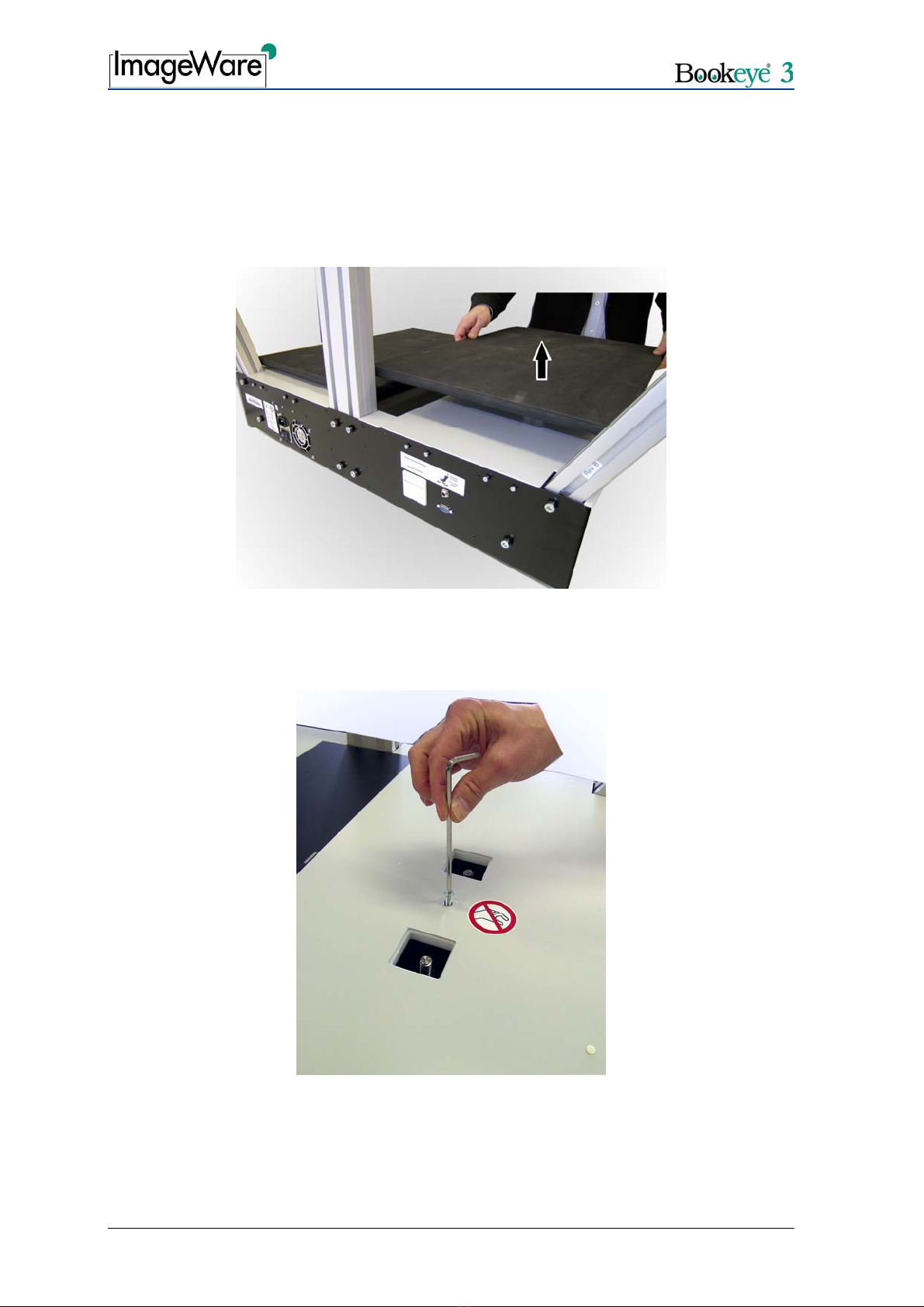
Picture 3: Removing the book cradle plates........................................................................ 8
Picture 4: Removing the screw............................................................................................ 8
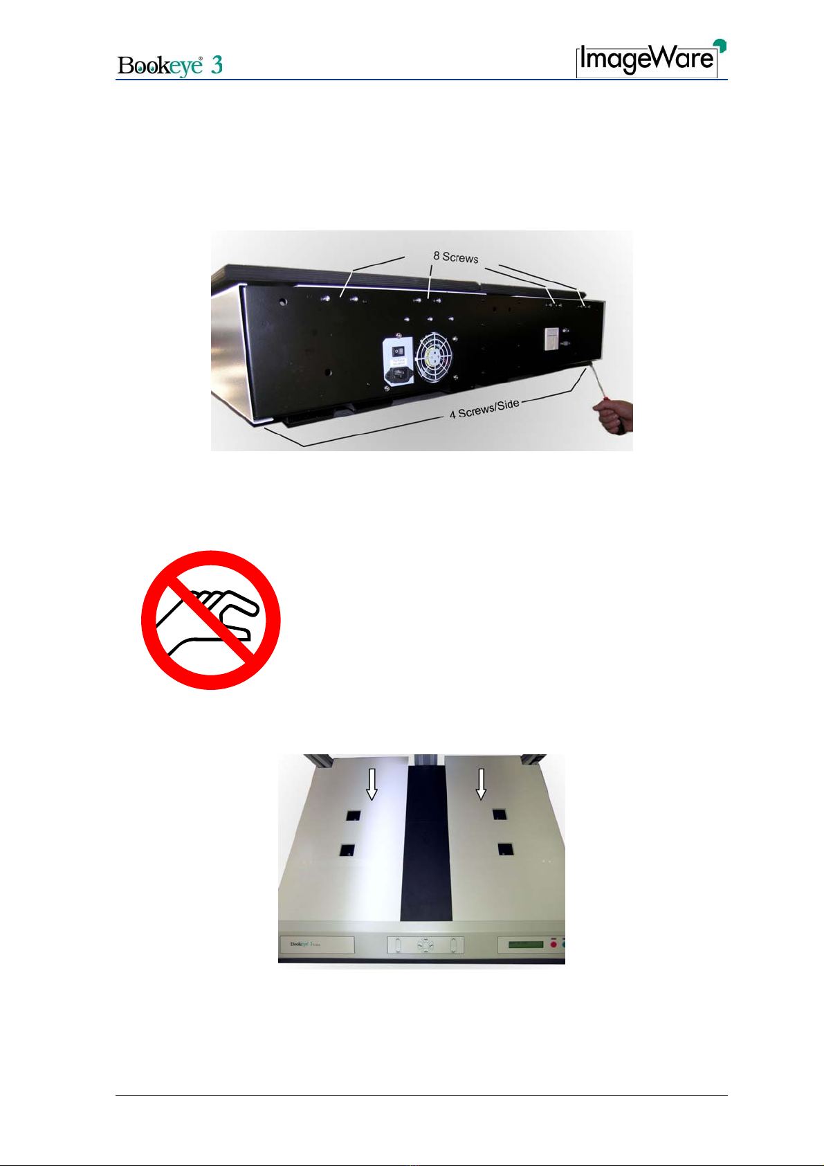
Picture 5: Screws at the rear panel and at the bottom of the body element........................ 9
Picture 6: Moving the cover................................................................................................. 9
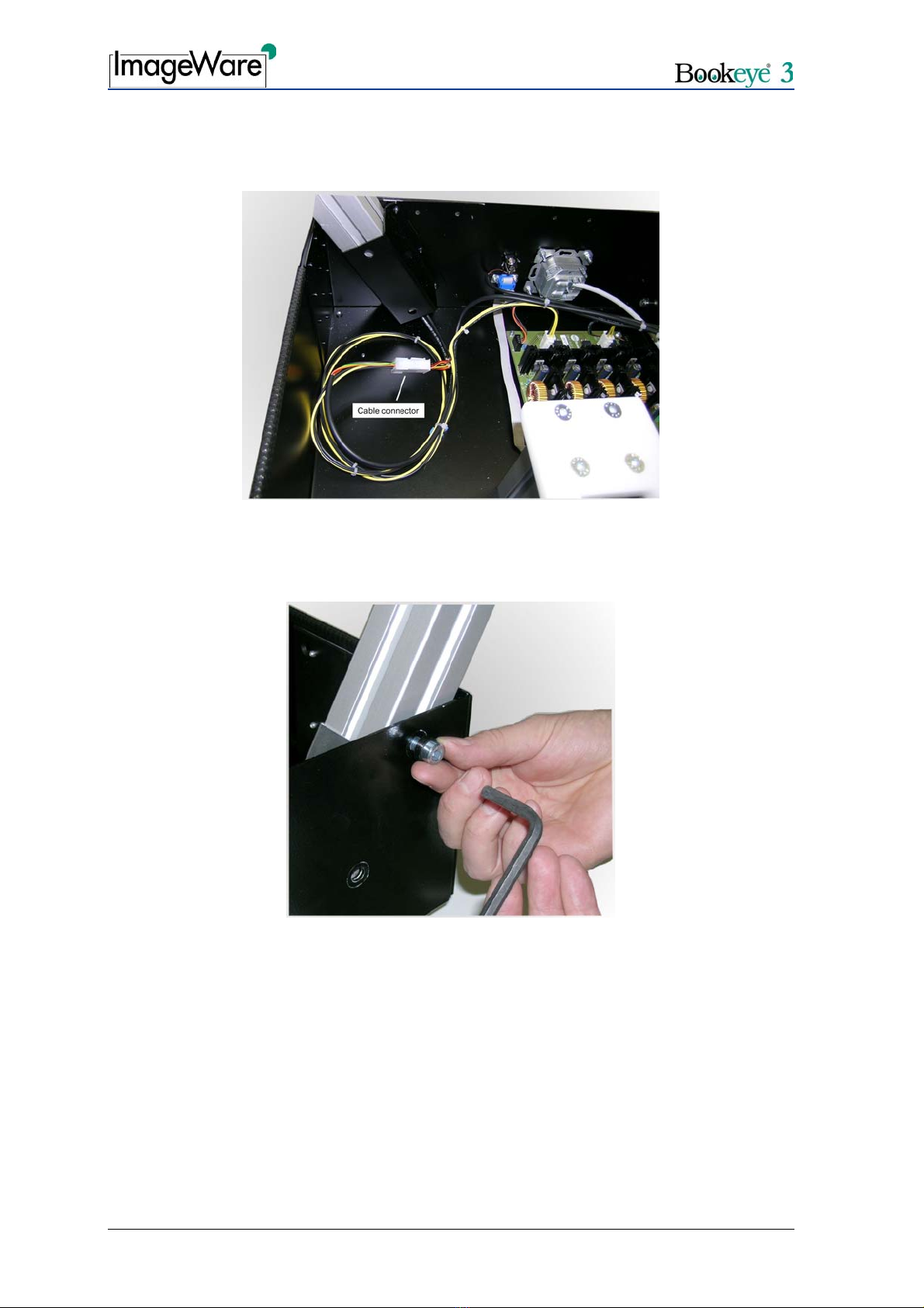
Picture 7: Lamp cable connector....................................................................................... 10
Picture 8: Hexagon socket head screws of the lamp ........................................................ 10
Picture 9: Assembling gas spring to lamp ......................................................................... 11
Picture 10: Detail view of left mounting bracket with bearing ............................................ 12
Picture 11: Glass plate on book cradle plates................................................................... 13
Picture 12: Borehole position ............................................................................................ 13
Picture 13: Holder assembled to lamp .............................................................................. 14
Picture 14: Detail view of mounting bracket ...................................................................... 14
Picture 15: Gas spring assembled to mounting bracket.................................................... 15
Picture 16: Setting the opening position............................................................................ 15
Picture 17: Setting the brake power .................................................................................. 16
Picture 18: “Start” screen .................................................................................................. 17
Picture 19: “Login level” screen......................................................................................... 17
Picture 20: “Install Option” screen ..................................................................................... 18
Picture 21: Login screen.................................................................................................... 19
Picture 22: User screen..................................................................................................... 19
Picture 23: “User Settings” screen .................................................................................... 20
Picture 24: “Poweruser main menu” screen ...................................................................... 22
Picture 25: “Adjustment & Support“ screen ....................................................................... 22
Picture 26: “Auto Focus” screen........................................................................................ 23
Picture 27: “White Balance” screen................................................................................... 24

Glass Plate Setup and Assembly Manual Page 7
A Hardware Setup
A.1 Content on Delivery
Picture 1: Assembly material of the glass plate option
The optional glass plate is delivered with the following material:
— 2x Mounting brackets
— 4x Plastic washers
— 2x T-slot nuts
— 2x Hexagon socket head screws
— 2x Gas springs
The glass plate comes with pre-assembled mounting brackets on the left and right rear
side. It also has two handles on the left and right front side.
Picture 2: Glass Plate

Page 8 Glass Plate Setup and Assembly Manual
A.2 Preparation Steps
To assemble the glass plate to the Bookeye®3 the following steps have to be performed:
1. Remove the book cradles. Pull the book cradle plates upwards from the driving
elements.
Picture 3: Removing the book cradle plates
2. Remove the hexagonal socket screws M6x16 located between the openings of the
driving elements. Use the Allen wrench, size 4 mm.
Picture 4: Removing the screw

Glass Plate Setup and Assembly Manual Page 9
For easy access to the screws at the bottom, place the device on the edge of the table.
3. Remove eight hexagonal socket head screws M4x10 on the rear panel.
4. Remove four hexagonal socket head screws M4x10 on the left and four on the right
side of the bottom.
Picture 5: Screws at the rear panel and at the bottom of the body element.
CAUTION!
Danger of injury!
Never put your fingers in the driving element openings.
5. Move the cover in direction of the arrows below for approx. 300 mm (≈12 inch).
This will give you access to the lamp holders.
Picture 6: Moving the cover

Page 10 Glass Plate Setup and Assembly Manual
6. Disconnect the lamp cable from its connector. The lamp cable connector is found
inside the main body at the bottom of the lamp holder bracket.
Picture 7: Lamp cable connector
7. Loosen and unscrew the two hexagonal socket head screws M8x12 on the rear panel
which hold each lamp.
Picture 8: Hexagon socket head screws of the lamp
8. Remove the lamps from the holders.
Table des matières


