IFM ANT424 Manuel utilisateur
Installation Instructions
RF identification system
Read/write head
ANT424
ANT425
80278720 / 00 10 / 2018
UK

2
Content
1 Preliminary note���������������������������������������������������������������������������������������������������4
1�1 Symbols used �����������������������������������������������������������������������������������������������4
2 Safety instructions �����������������������������������������������������������������������������������������������4
2�1 General���������������������������������������������������������������������������������������������������������4
2�2 Radio equipment ������������������������������������������������������������������������������������������5
2�3 Interference of electronic and medical devices ��������������������������������������������5
3 Functions and features ����������������������������������������������������������������������������������������5
4 Functions �������������������������������������������������������������������������������������������������������������5
4�1 Operating principle ���������������������������������������������������������������������������������������5
4�2 Overview�������������������������������������������������������������������������������������������������������6
5 Installation������������������������������������������������������������������������������������������������������������6
5�1 General installation instructions��������������������������������������������������������������������6
5�2 Notes on ID tag mounting�����������������������������������������������������������������������������6
5�3 Avoiding interference ������������������������������������������������������������������������������������7
5�4 Mechanical design����������������������������������������������������������������������������������������7
5�5 Fixing ������������������������������������������������������������������������������������������������������������7
5�6 Mounting distances���������������������������������������������������������������������������������������8
5�6�1 ANT424�������������������������������������������������������������������������������������������������8
5�6�2 ANT425�������������������������������������������������������������������������������������������������8
5�7 Positioning of the ID tags������������������������������������������������������������������������������9
5�7�1 ANT424�������������������������������������������������������������������������������������������������9
5�7�2 ANT425�������������������������������������������������������������������������������������������������9
6 Electrical connection������������������������������������������������������������������������������������������10
6�1 Wiring ���������������������������������������������������������������������������������������������������������10
6�2 cULus ���������������������������������������������������������������������������������������������������������10
7 Display elements ����������������������������������������������������������������������������������������������� 11
8 Operation����������������������������������������������������������������������������������������������������������� 11
9 Dimensions��������������������������������������������������������������������������������������������������������12
9�1 ANT424�������������������������������������������������������������������������������������������������������12
9�2 ANT425�������������������������������������������������������������������������������������������������������12
10 Technical data��������������������������������������������������������������������������������������������������12

3
UK
11 Maintenance, repair and disposal ��������������������������������������������������������������������12
12 Approvals/standards ����������������������������������������������������������������������������������������13
12�1 Radio approvals����������������������������������������������������������������������������������������13
12�1�1 Overview�������������������������������������������������������������������������������������������13
12�1�2 Europe ����������������������������������������������������������������������������������������������13
12�1�3 EC declaration of conformity ������������������������������������������������������������13

4
1 Preliminary note
This document is part of the device and contains information about the correct
handling of the product�
This document is intended for specialists� These specialists are people who are
qualified by their training and their experience to see risks and to avoid possible
hazards that may be caused during operation or maintenance of the device�
Read this document before use to familiarise yourself with operating conditions,
installation and operation� Keep this document during the entire duration of use of
the device�
1.1 Symbols used
►Instructions
→Cross-reference
Important note
Non-compliance can result in malfunction or interference�
Information
Supplementary note
2 Safety instructions
2.1 General
Observe the operating instructions� Non-observance of the instructions, operation
which is not in accordance with use as prescribed below, wrong installation or
incorrect handling can affect the safety of operators and machinery�
The installation and connection must comply with the applicable national and
international standards� Responsibility lies with the person installing the device�
The device must only be installed, connected and put into operation by a qualified
electrician as the safe function of the device and machinery is only guaranteed
when installation is correctly carried out�
Disconnect the unit externally before handling it�
In case of malfunction of the device or uncertainties please contact the
manufacturer� Tampering with the device can seriously affect the safety of
operators and machinery� This is not permitted and leads to an exclusion of liability
and warranty�

5
UK
2.2 Radio equipment
In general, radio equipment must not be used in the vicinity of petrol stations, fuel
depots, chemical plants or blasting operations�
►Do not transport and store any flammable gases, liquids or explosive
substances near the unit�
2.3 Interference of electronic and medical devices
Operation can affect the function of electronic devices that are not correctly
shielded�
►Disconnect the device in the vicinity of medical equipment�
►Contact the manufacturer of the corresponding device in case of any
interference�
3 Functions and features
In connection with the evaluation unit DTE10x the read/write head ANT424/
ANT425 enables non-contact reading and/or writing of the RFID transponders
(ID tags) conforming to the system�
The data is converted into digitally coded values and provided to the evaluation
unit�
4 Functions
4.1 Operating principle
The ID tags are operated passively, i�e� without battery� The energy required for
operation is supplied by the read/write head�
The physical principle of the energy transfer is based on inductive coupling� The
integrated antenna coil in the read/write head generates a magnetic field which
partly penetrates the antenna coil of the ID tag� A voltage is generated by induction
that supplies the data carrier with energy�
6
4.2 Overview
Art� no�:
Function:
Type designation:
Operating frequency:
Type:
Max� transmission power:
ANT424
Read/write head
DTRHF GBRWIDUS03
13�56 MHz
M18, flush mountable
200 mW
Art� no�:
Function:
Type designation:
Operating frequency:
Type:
Max� transmission power:
ANT425
Read/write head
DTRHF GNRWIDUS03
13�56 MHz
M18, non-flush mountable
200 mW
5 Installation
5.1 General installation instructions
When mounting several read/write heads adhere to the minimum distances
between the systems�
Flush mounting of a read/write head in metal reduces the read/write
distance�
The immediate vicinity of powerful HF emission sources such as welding
transformers or converters can affect operation of the read/write heads�
Information on the available mounting accessories is available on our website at:
www�ifm�com
5.2 Notes on ID tag mounting
If the ID tags are mounted in/on metal, the read/write distance is reduced�
For positioning the ID tags the read/write heads are marked with an
antenna symbol on the active face� It designates the middle of the
integrated antenna coil and has to correspond with the middle of the ID tag�

7
UK
The orientation of the read/write head antenna axis must correspond with
the axis of the ID tag coil�
The best way to position the available ID tags and on mounting in metal is
available on our website: www�ifm�com
5.3 Avoiding interference
The device generates a modulated electrical field with a frequency of 13�56 MHz�
To avoid interference of the data communication no other devices generating
interference emission in this frequency band must be operated in the vicinity� Such
devices are for example frequency converters and switched-mode power supplies�
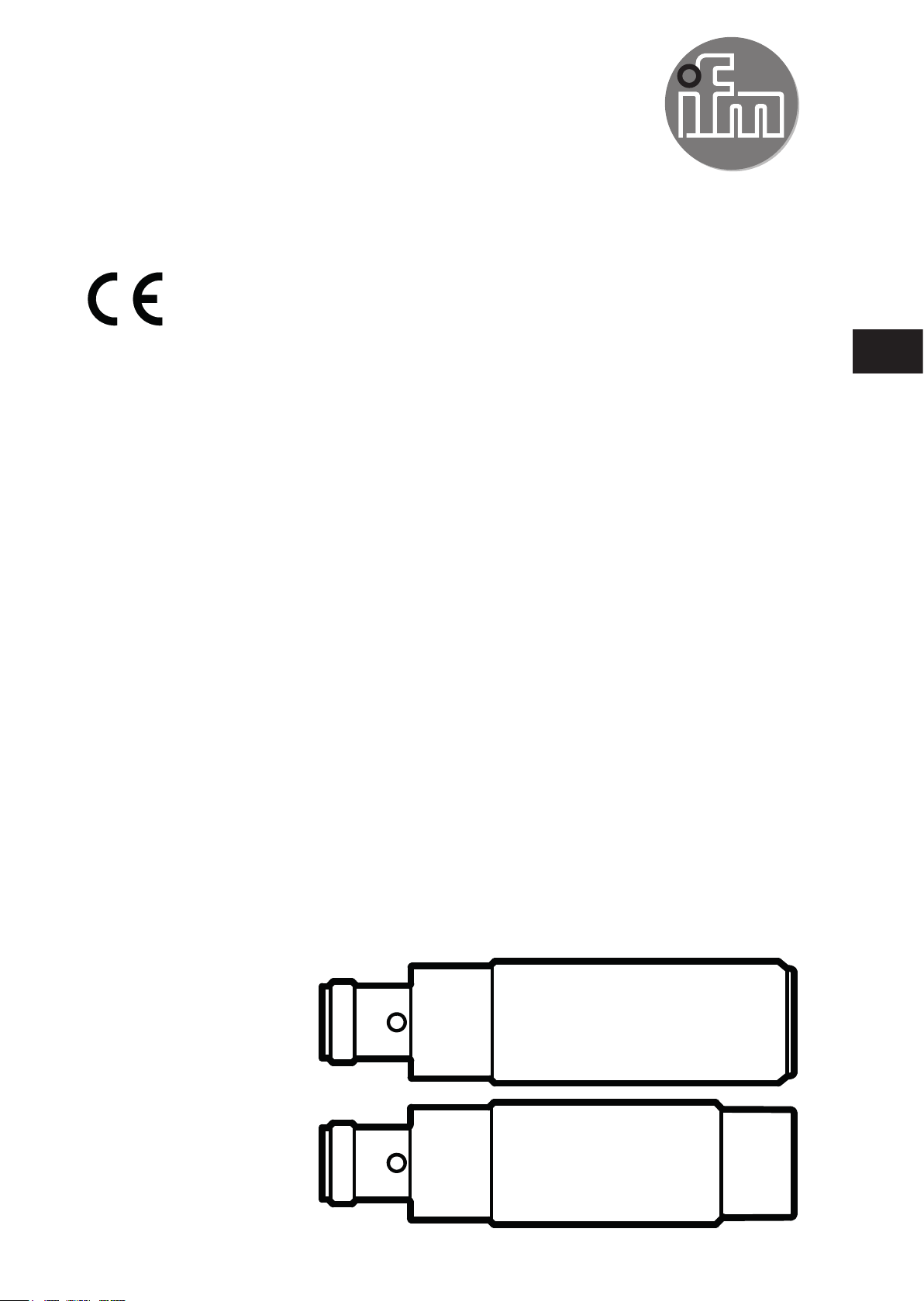
5.4 Mechanical design
1: Sensing face (ANT424) 1: Sensing face (ANT425)
5.5 Fixing
►Fix the device using the supplied nuts (M18)�
flush (ANT424) non-flush (ANT425)

8
5.6 Mounting distances
5.6.1 ANT424
Operating mode Distance side (A) Distance front (B)
For reading and writing ≥ 60 mm ≥ 100 mm
5.6.2 ANT425
Operating mode Distance side (A) Distance front (B)
For reading and writing ≥ 90 mm ≥ 180 mm
9
UK
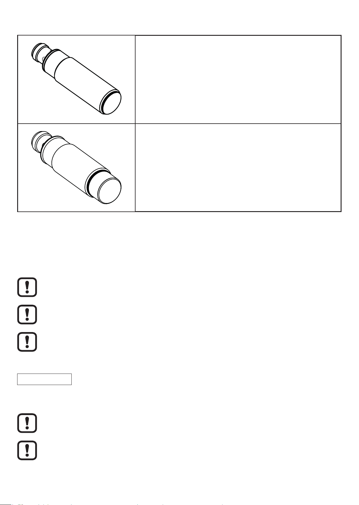
5.7 Positioning of the ID tags
5.7.1 ANT424
D
►Align the ID tag on the antenna central axis�
Distance read/write head (D)
ID tag Type plastics
E80371 16 mm
All indications apply to static read/write operations�
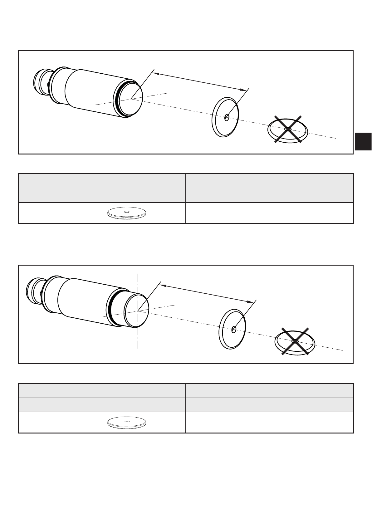
5.7.2 ANT425
D
►Align the ID tag on the antenna central axis�
Distance read/write head (D)
ID tag Type plastics
E80371 40 mm
All indications apply to static read/write operations�

10
6 Electrical connection
ATTENTION
The unit must be connected by a qualified electrician�
Device of protection class III (PC III)
The electric supply must only be made via PELV/SELV circuits�
►Disconnect power before connecting the unit�
6.1 Wiring
►Connect the device to the evaluation unit DTE10x using the M12 connection�
Voltage is supplied via the evaluation unit�
4
1
3
L+
1
3
4
L
DATA
A selection of sockets is available on our website at: www�ifm�com
Cables with the following characteristics are suitable for the connection:
Length Ohmic resistance (feed + return line) Effective cable capacity
< 20 m max. 3Ω max� 3 nF
Ce manuel convient aux modèles suivants
1
Table des matières
Autres manuels IFM Contrôleurs d'accès IP


