IBT Technologies FWA8206 Series Mode d'emploi

FWA8206 Series
Network Appliance
User′s Manual
Version: 1.1

FWA8206 Series User’s Manual
1
Table of Contents
Chapter 1 Introduction ...................................................................................................................3
Chapter 2 System Specification...................................................................................................4
Chapter 3 Hardware Configuration..............................................................................................5
Chapter 4 Console Mode Information.........................................................................................7
Chapter 5 Opening the chassis....................................................................................................9
Chapter 6 Removing and Installing DIMM ...............................................................................10
Chapter 7 Removing and Installing CompactFlash Card.....................................................11
Chapter 8 Removing and Installing the Battery.....................................................................12
Chapter 9 Installing the 3.5” HDD..............................................................................................13
Chapter 10 Installing the 2.5” HDD..............................................................................................14
Chapter 11 BIOS Information........................................................................................................15
Chapter 12 Bypass Information....................................................................................................28
Chapter 13 Factory Default Information.....................................................................................31
Chapter 14 GPO LED Information................................................................................................33
Chapter 15 System Architecture..................................................................................................36

FWA8206 Series User’s Manual
2
Foreword
To prevent damage to the system board, please handle it with care and follow the measures below,
which are generally sufficient to protect your equipment from static electricity discharge:
When handling the board, use a grounded wrist strap designed for static discharge elimination grounded
to a metal object before removing the board from the antistatic bag. Handle the board by its edges only;
do not touch its components, peripheral chips, memory modules or gold contacts.
When handling processor chips or memory modules, avoid touching their pins or gold edge fingers.
Return the Network Appliance system board and peripherals back into the antistatic bag when not in use
or not installed in the chassis.
Some circuitry on the system board can continue to operate even though the power is switched off.
Under no circumstances should the Lithium battery cell used to power the real-time clock be allowed to
be shorted. The battery cell may heat up under these conditions and present a burn hazard.
WARNING!
1. "CAUTION: DANGER OF EXPLOSION IF BATTERY IS INCORRECTLY REPLACED.
REPLACE ONLY WITH SAME OR EQUIVALENT TYPE RECOMMENDED BY THE
MANUFACTURER. DISCARD USED BATTERIES ACCORDING TO THE
MANUFACTURER’S INSTRUCTIONS"
2. This guide is for technically qualified personnel who have experience installing and configuring
system boards. Disconnect the system board power supply from its power source before you
connect/disconnect cables or install/remove any system board components. Failure to do this can
result in personnel injury or equipment damage.
3. Avoid short-circuiting the lithium battery; this can cause it to superheat and cause burns if touched.
4. Do not operate the processor without a thermal solution. Damage to the processor can occur in
seconds.
5. Do not block air vents at least minimum 1/2-inch clearance required.

FWA8206 Series User’s Manual
3
Chapter 1 Introduction
The FWA8206 series was specifically designed for the network security &
management market.
Network Security Applications:
• Firewall
• Virtual Private Network
• Proxy Server
• Caching Server
Network Management Applications:
• Load balancing
• Quality of Service
• Remote Access Service
The FWA network appliance product line covers the spectrum from offering
platforms designed for :
• SOHO
• SMB
• Enterprise
Each product is designed to address the distinctive requirements of its
respective market segment from cost effective entry-level solutions to
high throughput and performance-bound systems for the Enterprise level.

FWA8206 Series User’s Manual
4
Chapter 2
System Specification
Project Name FWA8206
Construction 19” 1U Rackmount
Processor Intel®Core 2 Quad / Core 2 Duo / Core 2 Extreme
Conroe, Conroe-L, Conroe XE, Allendale, Wolfdale,
Kentsfield, Kentsfield XE, Yorkfield XE processors.
With FSB 800/1066/1333 MHz
Memory Support DDR2 667/800 SDRAM, up to 8GB
Chipset North Bridge : Intel Q35
South Bridge : Intel ICH9 I/O Controller Hub
Ethernet Onboard:
Intel®82574L Gigabit Ethernet controllers x6 with RJ-45
connector
Eth0 & Eth1 with hardware Bypass
Expansion slots PCI expansion slot x2
Storages Support 3.5” SATA HDD x1 , CF card x1 , DOM x1
Front I/O USB 2.0 ports x 2
DB-9 x 1 for Console
Power LED
HDD Access LED
Bypass LED
GPO LED ID1~5
Factory Default switch
Reset switch
Support LCM/Key pad module (IBASE proprietary)
Hardware Monitor Voltage, Temperature
Power Supply 300W ATX, Full Range
Dimensions 88 mm (H) x 430 mm (W) x mm (D)
Operating
Environment
Temperature : 0 ~ 40℃
Humidity : 20% ~ 90%
Storage Environment Temperature : 0 ~ 70℃
Humidity : 5% ~ 95%
Chapter 3 Hardware Configuration

FWA8206 Series User’s Manual
5
CPU board layout
Jumper Setting
JP16: Clear CMOS Contents JP1, JP2: Watchdog Timer & LAN1/LAN2 Bypass Settings
JP16:1-2 Normal (Default) JP1 & JP2 : JP2 Pin 1-2 & 3-4 Open JP1 Pin 1-2 Closed
System will bypass LANs upon the time
out of watchdog timer
2-3 Clear CMOS
JP1 & JP2 : JP2 Pin 1-2 & 3-4 OpenJP1 Pin 2-3 Closed
System LANs bypass function controlled by SIO
GPIO15.
JP1 & JP2 : JP2 Pin 1-2 & 3-4 ClosedJP1 Pin 1-2 Closed (Default)
System will reboot upon the time out of watchdog
timer.

FWA8206 Series User’s Manual
6
JP9 : Configure and Recovery (Factory use only) JP17:Power ON Setting
Pin 1-2 Short/Closed: Normal (default) Pin 1-2 Short/Closed: Power on by power supply AC
on
Pin 2-3 Short/Closed: Configure Pin 2-3 Short/Closed: Power on by system button
Open: Recovery
Rear Panel Features
Front Panel Features
Note :
The NBP LED means None ByPass function.
If NBP LED turns on, it indicates Normal mode.
If NBP LED turns off, it indicates Bypass mode.
FWA8206 Series User’s Manual
7
Chapter 4 Console Mode Information
FWA8206 supports output information via Console in BIOS level.
Prepare a computer as client loaded with an existing OS such Windows XP.
Connect client computer and FWA8206 with NULL Modem cable.
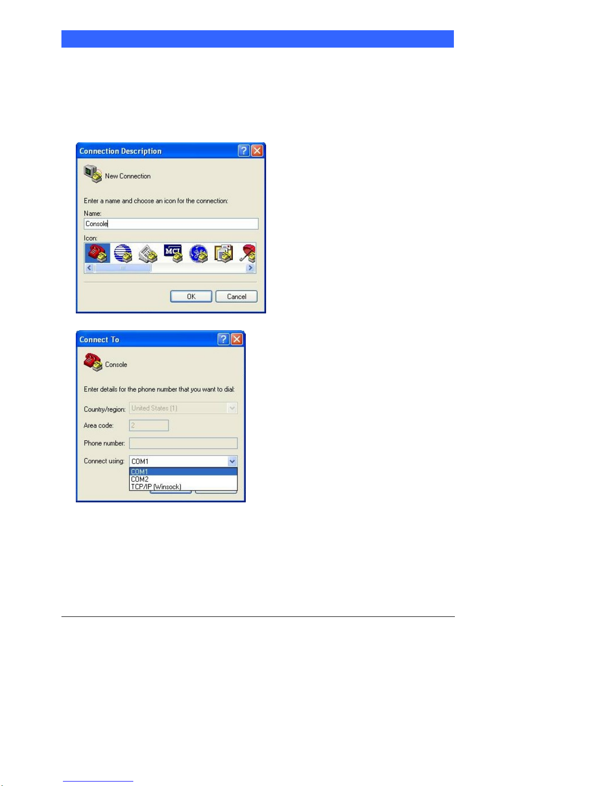
Follow the steps below to configure the Windows Hyper Terminal application setting:
1. For executing the Hyper Terminal, issue command “hypertrm”.
2. Customize your name for the new connection.
3. Choose the COM port on the client computer for the connection.
4. Please make the port settings to Baud rate 19200, Parity None, Data bits 8, Stop bits 1

FWA8206 Series User’s Manual
8
5. Power up the FWA8206, and the screen will display the following information.
6. Press <Tab> key to enter BIOS setup screen in Console mode.
Press <Del> key to enter BIOS setup screen in VGA mode.
FWA8206 Series User’s Manual
9
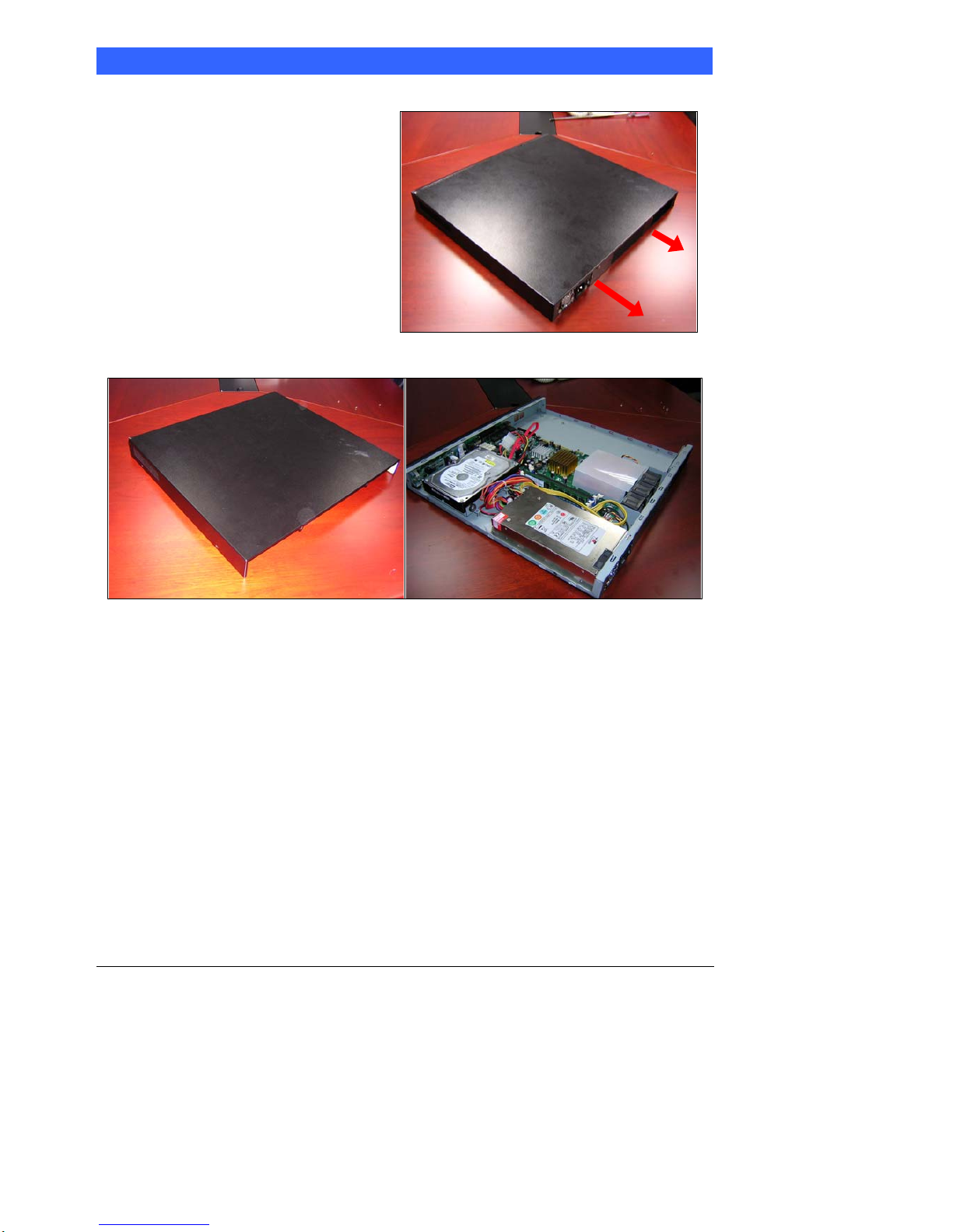
Chapter 5 Open the chassis
1. Loosen the two screws of the chassis
on the back to remove the top lead
(Fig. 5-1).
Fig. 5-1 Take off screws
2. The top lead (Fig. 5-2) can be removed from the base stand (Fig. 5-3).
Fig. 5-2 The top lead Fig. 5-3 The base stand
Table des matières
Manuels Matériel réseau populaires d'autres marques

Matrix Switch Corporation
Matrix Switch Corporation MSC-HD161DEL Manuel utilisateur

B&B Electronics
B&B Electronics ZXT9-IO-222R2 Manuel utilisateur

Yudor
Yudor YDS-16 Manuel utilisateur

D-Link
D-Link ShareCenter DNS-320L Manuel utilisateur

Samsung
Samsung ES1642dc Instructions d'utilisation

Honeywell Home
Honeywell Home LTEM-PV Instructions de montage


