HydroQuip BALBOA BP7 Series Manuel utilisateur

BP SERIES
BALBOA®
TM
Balboa BP7 SERIES
Installation/Operation Manual
By
•
•

Contents
Power Connection.................................................8
Wi-Fi Option Installation.......................................11
System Setup & Connections..........................14-15
TP400/600 Programming.....................................16
TP500/TP500S Programming..............................17
Circuit Board Configuration..................................12
TP800/900/spaTouch Programming....................18
Electrical Installation...........................................5-7
Circuit Board Wiring Diagram...............................13
GFCI Wiring Detail.................................................7
Pump Cord Configuration......................................9
Important Safety Instructions..............................3-4
Spaside Installation.............................................10
spaTouch (Icon) Programming.............................19
System Start-Up...................................................20
System Plug Pinouts.............................................24
Troubleshooting..............................................25-26
Operational Considerations..................................21
System Data Label...............................................27
System Functions / Features...........................22-23
Testing/Replacing Sensors........... .......................24
Warranty Information............................................27

3
IMPORTANT SAFETY INSTRUCTIONS
DANGER To reduce the risk of injury, do not permit children to use this product
unless they are closely supervised at all times.
WARNING - RISK OF CHILD DROWNING. Extreme caution must be exercised to
prevent unauthorized access by children. To avoid accidents, ensure that children
cannot use a spa or hot tub unless they are supervised at all times.
DANGER To reduce the risk of injury to persons, do not remove suction fittings.
Spa location must accommodate sufficient drainage of water around the base of the
structure, as well as the power source compartment.
Prolonged immersion in water that is warmer than normal body temperature can result
in a dangerous condition known as HYPERTHERMIA. The causes, symptoms,
and effects of hyperthermia may be described as follows: Hyperthermia occurs
when the internal temperature of the body reaches a level several degrees above
the normal body temperature of 98.6BF. The symptoms of hyperthermia include
dizziness, fainting, drowsiness, lethargy, and an increase in the internal
temperature of the body. The effects of hyperthermia include (1) unawareness of
impending hazard, (2) failure to perceive heat, (3) failure to recognize the need to
exit spa, (4) physical inability to exit spa, (5) fetal damage in pregnant women, (6)
unconsciousness resulting in danger of drowning. WARNING The use of alcohol,
drugs or medication can greatly increase the risk of fatal hyperthermia in hot tubs
and spas.
DANGER - RISK OF ELECTRICAL SHOCK.
A spa may be installed within 5 feet of metal surfaces if each metal surface is
permanently connected by a solid copper conductor attached to the wire connector
on the terminal box . Refer to NEC and local codes
A bonding lug is provided on the control box to permit connection of a
solid copper bonding conductor between this point and any equipment, metal
enclosures of electrical equipment, metal water pipe, or conduit within 5 feet
(1.5m) of the unit as needed to comply with local requirements.
Bond accessible metal to the dedicated connector on the equipment grounding bus,
bond the equipment ground bus to the local common bonding grid as part of the
installation in the form of (1) a reinforced concrete slab for support, (2) a ground
plate provided beneath the hot tub or spa, or (3) a permanent ground connection
that is acceptable to the local inspection authority.
DANGER RISK OF ELECTRICAL SHOCK. Do not permit any electrical appliance,
such as a light, telephone, radio, or television, within 5 feet (1.5m) of a spa or hot
tub.
To reduce the risk of injury:
The water in a spa or hot tub should never exceed 104BF (40BC). Water temperatures
between 100BF (38BC) and 104BF (40BC) are considered safe for a healthy adult.
Lower water temperatures are recommended for extended use (exceeding 10-15
minutes) and for young children.
Excessive water temperatures have a high potential for causing fetal damage during
the early months of pregnancy, pregnant or possibly pregnant women should limit
spa or hot tub water temperatures to 100BF(38BC).
!
!
!
!
!
Before entering the spa or hot tub, the user should measure the water temperature
with an accurate thermometer.
The use of alcohol, drugs, or medication before or during spa or hot tub use may lead
to unconsciousness with the possibility of drowning.
Persons suffering from obesity or with a medical history of heart disease, low or high
blood pressure, circulatory system problems, or diabetes should consult a
physician before using a spa or hot tub.
in effect at the time of
installation.)

4
Persons using medication should consult a physician before using a spa or hot tub
since some medication may affect heart rate, blood pressure, and circulation.
A terminal marked “G” or “ground” is provided in the wiring box located inside the
equipment compartment. To reduce the risk of electric shock, connect the
terminal or connector to the grounding terminal of your electrical service or supply
panel with a continuous green insulated copper wire in accordance with National
Electric Code Table 250-95 and any other local codes in effect at the time of the
installation.
The electrical supply for this product must include a suitably rated switch or circuit
breaker to open all ungrounded supply conductors to comply with Section 422-30
of the National Electric Code, ANSI/NFPA 70 1987. The disconnecting means
must be readily accessible to the tub occupant but installed at least 5 feet (1.5m)
from the tub water.
WARNING - Do not install indoors. This unit uses a gas heater that requires proper
ventilation and is intended for outdoor use only.
For Permanently Installed Units
For Permanently Installed Units not Provided with an Internal Disconnecting Method
For Units with Gas Heaters
ONLY EXPERIENCED TECHNICIANS SHOULD SERVICE THIS EQUIPMENT.
HIGH VOLTAGE CAN SERIOUSLY INJURE OR KILL!
DO NOT remove the protective covers from any electrical enclosure, or attempt to service any related
electrical device, unless you are a qualified electrician or service professional.
WARNING
All electrical work must be performed by a qualified electrician and must conform to all local
codes.
IMPORTANT
Due to the danger of severe electrical shock, locate all power disconnects before servicing a
spa. Precautions must be taken whenever working with breaker boxes, G.F.C.I.’s, or service
disconnects.
DANGER
Risk of electric shock. Before working with any electrical connections, make certain that the
Main Power breaker from the house breaker box has been turned off.
High Voltage Warning
Must be connected to a grounded, grounding type receptacle only. NEVER connect
the spa to an extension cord.
Do not bury the cord.
For Cord and Plug Connected Units
IMPORTANT SAFETY INSTRUCTIONS

5
Electrical Installation
15A 20A 30A 40A 50A 60A
12A
16A 24A
32A 40A 48A
14 12 10 86 4
Circuit & Breaker
Rating
Maximum Amps
Minimum Wire
Size
The GFCI (Ground Fault Circuit Interrupter) is a mandatory electrical safety device required for all
portable spas and hot tubs as specified in the National Electrical Code Article 680-42. The GFCI
in your particular installation may be installed at the electrical service panel or a separate sub-
panel.
Use copper conductors ONLY. The ground must be sized following the National Electric Code,
Table 250-122. For Power conductor size, refer to the National Electric Code Table 310-16.
A bonding lug has been provided on the control box to allow connection to local ground
points. To reduce the risk of electrical shock, a solid copper bonding wire should be
connected from this lug to any metal objects within 5 feet of the spa.
A licensed electrician must accomplish the electrical installation in accordance with the National
Electric Code(NEC) Article 680, and any local codes in effect at the time of installation.
The NEC and most local codes require that a “disconnect” be installed within “line-of-site” of
the spa.
Refer to the System Data Label for equipment voltage and maximum amperage draws.
IMPORTANT- If your electrician is not absolutely sure how to connect your system
correctly, call your local dealer. Any mistake may be costly and void your equipment
warranty.
The above table is a wiring chart representation.
CAUTION: Damage may occur to the circuit board and spaside if the spaside plug
is not properly aligned to the receptacle on the circuit board or if the spaside plug
is connected or disconnected while the power is on.
**Any resulting damages are not covered under manufacturer’s warranty**
**Any resulting damages are not covered under manufacturer’s warranty**
CAUTION: Do not connect or disconnect any components while the power is on.
All connections must be done with the power off as it may cause damage to the
system.

6
Electrical Installation
MAIN BREAKER PANEL
LINE 1
N
LINE 2
OPTION 1
MAIN BREAKER PANEL
OPTION 2
20-60AMP HARDWIRED
Option 1 shows the power from GFCI breaker installed into main service panel to a service disconnect
within line-of-site of the spa. If the manufacturer of your homes main breaker panel makes a GFCI
breaker, you may be able to add it to an open slot in the panel.
Option 2 shows the power from main service panel to a GFCI subpanel within line-of-site of the spa.
(Note: Most local codes will allow a GFCI subpanel to be a disconnect. If this is not the case in your
installation, a disconnect must be provided.)
REFER TO GFCI WIRING DETAIL ON PAGE 8
GFCI Installed in Main Service Panel
Subpanel GFCI Installed
PORTABLE SPA
INLINE SPA DISCONNECT
20-60AMP HARDWIRED
GFCI DISCONNECT
LINE 1
N
LINE 2
INLINE SPA DISCONNECT
TO PORTABLE SPA
REFER TO GFCI WIRING DETAIL ON PAGE 8

7
It is important that the GFCI circuit breaker is installed correctly. Often this component has
been improperly installed causing the breaker to instantly trip when the system is turned on.
Below is an illustration of a typical GFCI breaker installation.
WARNING: Refer to the circuit breaker manufacturers installation instructions. This
illustration is meant to be a guide for Field Technicians and is not intended to
override or substitute the instructions supplied with the circuit breaker.
GFCI
TEST
(Ground Fault Circuit Interrupter)
CIRCUIT BREAKER
NEUTRAL PIGTAIL
NEUTRAL BUS BAR
LINE 1
NEUTRAL
LINE 2
GROUND
GROUND BUS BAR
LINE LUG #1 LINE LUG #2 INCOMING
SERVICE
CONDUCTORS
FROM
MAIN
PANEL
NEUTRAL
GROUND
TO SPA CONTROL SYSTEM
LOAD
LOAD NEUTRAL MUST BE CONNECTED
DIRECTLY TO GFCI AS SHOWN
GFCI Wiring Detail
(The spa must be installed on a dedicated circuit.)
This illustration depicts a typical 15 AMP, cord-end GFCI installation.
If your system was configured to include a 120VAC power cord, ensure that the proper
receptacle has been installed (a dedicated circuit is required). DO NOT under any
circumstances modify a 20 Amp plug to fit into a 15 Amp receptacle or use an extension
cord. Doing so will create hazardous conditions and/or invalidate the warranty.
OPTION 3
15/20AMP CORD END GFCI
15A / 120V OUTLET
PORTABLE SPA
MAIN BREAKER PANEL
DEDICATED
Units with 15A / 20A GFCI Plug Connection
Electrical Installation
LINE 1
LINE 2

8
240-VOLT ELECTRICAL SERVICE REQUIREMENTS
If supply circuit allows move DIP switches A2
& A3 to the on or up position to place the
system in high amp mode. High amp mode
allows the heater to stay on when high speed
pump(s) or blower is turned on.
ŸUse copper conductors only as required by the NEC.
IMPORTANT: Always refer to the product data label (located on top of the control box) for
specific electrical information.
ŸSecure wires as defined by the NEC and in compliance with any local codes in effect at
the time of installation.
IMPORTANT- All equipment must be rated for 240VAC
unless Neutral is connected and components are
converted appropriately.
.
Power Connection
Ground
Lug
OPTIONAL (N)
L2
L1
GR
N/A
BLK (L1)
RED (L2)
WHT (N)
120-VOLT ELECTRICAL SERVICE REQUIREMENTS
Assure DIP switches A2 & A3 are OFF or in the
down position to place the system in low amp
mode. Low amp mode disables the heater when
high speed pump(s) or blower is turned on to
prevent breaker tripping.
Ground
Lug
NEU
LINE
GR
N/A
BLK (L1)
RED (L2)
WHT (N)
TRANSFORMER
BEFORE AFTER
Step 1: Convert transformer to allow 120V input by installing an additional jumper** (Included
with system) at J24 located above the transformer
Step 2: Connect 120V input
power as shown
Step 3: Assure all component white wires are
connected at Area 2
**120V JUMPER HQ PT#: 34-20564 (included)

9
Black = Low Speed
Red = High Speed
White = Common
Green = Ground
SINGLE SPEED PUMP / ACCESSORY CORD CONFIGURATION
The following wiring configuration is for single-speed pump circuits, circulation pumps, ozones,
blowers and accessories.
Black = Hot/Line
White = Common
Green = Ground
Black = Hot/Line
White = Common
Green = Ground
Pump Cord Connections
Pump
Single Speed Device /
Accessories
System
System
2-SPEED PUMP CORD CONFIGURATION
The following wiring configuration is for two-speed pump circuits.
10
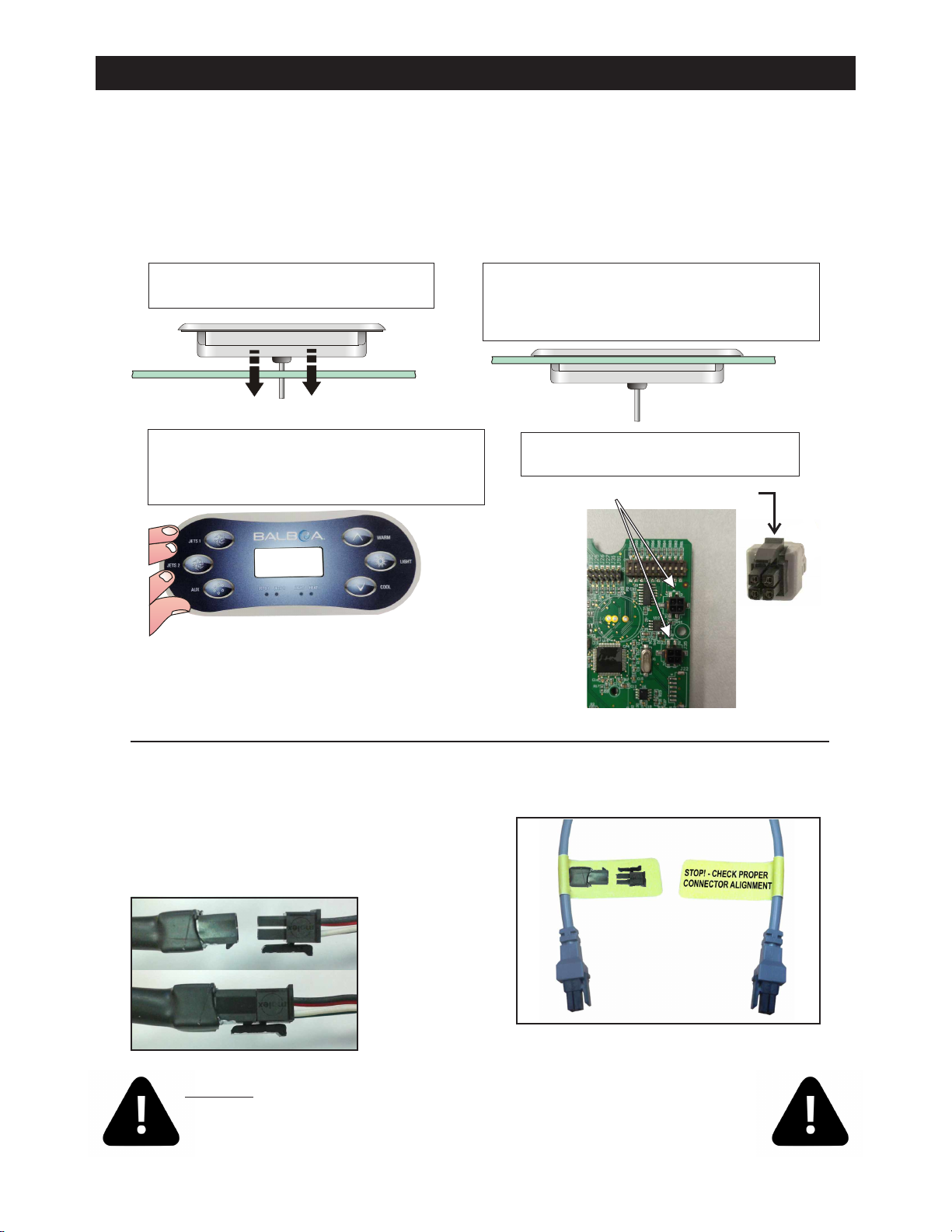
Step 4 - Connect spaside to an empty
connection marked MAIN. (Fig.4)
*Must align Locking Clip on spaside plug with
Locking Tab on circuit board for proper
function.
Locking Clip*Locking Tab*
Spaside
Plug
Fig.4
When utilizing a spaside
extension cord, the clip and
tab must also be aligned at all
connections. Fig.5
Fig.5
Cord plugs are labeled to insure proper
plug alignment as shown in Fig.6
Fig.6
Front side Back side
CONNECTING SPASIDE & EXTENSION
SPASIDE CONTROL INSTALLATION
Step 1 - Clean area and insert spaside
control. (Fig.1)
Overlay may vary
Step 2 - Remove the double sided adhesive
from the back of the spaside. Make certain the
spaside is straight and adhere to the spa shell.
(Fig.2)
ŸThe mounting area must be above the maximum water level of the spa and in an area with good
drainage to prevent any standing water on or around the spaside.
If required, you may have to cut out a hole in the spa shell to install spaside control.
ŸThe spaside should never be submerged.
ŸThe spaside should be protected from extended periods of exposure to sunlight.
Step 3 - Remove protective film from display
window then clean the face of the spaside.
Now carefully align and apply the label. (Fig.3)
Fig.3
Fig.1 Fig.2
CAUTION: Damage may occur to the circuit board and spaside if the spaside plug
is not properly aligned to the receptacle on the circuit board or if the spaside plug
is connected or disconnected while the power is on.
**Any resulting damages are not covered under manufacturer’s warranty**
Table des matières
Autres manuels HydroQuip Système de contrôle

HydroQuip
HydroQuip 9700 Series Mode d'emploi

HydroQuip
HydroQuip CS7100 Manuel utilisateur

HydroQuip
HydroQuip BALBOA CS6000B Series Manuel utilisateur

HydroQuip
HydroQuip PLATINUM PS-9003 Instructions d'utilisation d'origine

HydroQuip
HydroQuip Universal Air Series Manuel utilisateur

HydroQuip
HydroQuip WaterPro 622XB Manuel utilisateur

HydroQuip
HydroQuip 6500 Series Manuel utilisateur

HydroQuip
HydroQuip CS7500 Instructions de montage


