
Hydro-Gear RT-310 Manuel d'installation et d'exploitation

RT-310™
Service and Repair Manual
BLN-0078
February 2023


RT-310TM i
TABLE OF CONTENTS
SECTION PAGE
Tear down and reassembly.....................10-12
How to Use This Manual...................10
General Instructions..........................10
Tools..................................................11
Torques...............................................11
Removal............................................12
RT-310TM Tear Down and Assembly........13-25
Fan and Pulley Assembly..................13
Control Arm Assembly.......................14
Side Housing.....................................15
Motor Shaft........................................16
Motor Block Assembly and Thrust
Bearing..............................................17
Center Section..................................18
Pump Block.......................................19
Swash Plate and Thrust
Bearing..............................................20
Input Shaft.........................................21
Bypass Assembly..............................22
Assembly After Complete Tear
Down................................................23
RT-310TM Exploded View...................24
RT-310TM Parts List.............................25
Glossary of Terms......................................26
SECTION PAGE
Foreword.......................................................1
Description and Operation........................2-5
Introduction.........................................2
General Description ...........................2
External Features RT-310TM...................4
Technical Specifi cations......................5
Product Identifi cation...........................5
Safety.............................................................6
Personal Safety...................................6
Tool Safety...........................................6
Work Area Safety.................................6
Servicing Safety...................................6
Troubleshooting...........................................7
Service and Maintenance..........................8-9
External Maintenance.........................8
Service and Maintenance
Procedures..........................................8
Fluids...................................................8
Fluid Volume and Level.......................8
Purging Procedures............................9

RT-310TM 1
Headquartered in Sullivan, Illinois,
Hydro-Gear® is a world leader in the design,
manufacture, and service of quality hydrostatic
transaxles for the lawn and garden industry.
The mission of our company is to be recog-
nized by our customers and the industry as a
world-class supplier and the quality leader in
everything we do.
This Service and Repair Manual is designed
to provide information useful in servicing and
troubleshooting the Hydro-Gear® RT-310TM right
angle hydrostatic transmission.
Also included is a glossary of terms that are
frequently used throughout the industry and in
Hydro-Gear service publications. Understand-
ing terminology is very important!
It is necessary, and a good shop practice, that
your service area be equipped with the proper
tools and the mechanics be supplied the latest
information available. All repair procedures
illustrated in this guide are suggested, but pre-
ferred methods of repair.
Internal repair procedures require that the RT-
310TM right angle hydrostatic transmission be
removed from the vehicle.
This is not a certifi cation, test or study guide
for a certifi cation test. If a technician is inter-
ested in certifi cation, they should contact an
agent representing the EETC (Equipment and
Engine Training Council) at (262) 367-6700 or
their Hydro-Gear® Central Service Distributor.
Many distributors will be hosting certifi cation
testing. These study guides will cover most of
the products and manufacturers in our industry.
For more information about Hydro-Gear® or our
products, please contact your Central Service
Distributor, or call our Customer Service Depart-
ment at (217) 728-2581.
FOREWORD

2 RT-310TM
This transmission uses a variable displace-
ment pump with a maximum displacement
of 3cc per revolution, and motor with a fi xed
displacement of 10cc per revolution. The vari-
able displacement pump features a trunnion
mounted swashplate with a direct-proportional
displacement control. Reversing the direction
of the swashplate reverses the fl ow of oil from
the pump and thus reverses the direction of the
motor output rotation. The pump and motor are
of the axial piston design and utilize spherical
nosed pistons which are held against a thrust
race by internal compression springs.
The check valves in the center section are used
to control the makeup fl ow of the fl uid to the low
pressure side of the loop.
A hydraulic bypass is provided to allow the ve-
hicle to be moved without starting the engine.
The bypass lifts the check valves off their seat
allowing oil to freely fl ow. This permits moving
the vehicle for a short distance at a maximum
of 2 m.p.h. (3.2 Km/h) .
INTRODUCTION
The purpose of this manual is to provide infor-
mation useful in servicing the Hydro-Gear® RT-
310TM right angle hydrostatic transmission. This
manual includes general descriptions, hydraulic
schematics, technical specifi cations, servicing
and troubleshooting procedures.
The transmission normally will not require ser-
vicing during the life of the vehicle in which it
is installed. Should other servicing be required,
the exterior of the transmission will need to
be thoroughly cleaned before beginning most
procedures. Do not wash the transmission
while it is hot. It is best to not allow direct
spray from a pressure washer to clean the
transmission.
GENERAL DESCRIPTION
The RT-310TM is a self contained unit designed
for the transfer and control of power. It provides
an infi nitely variable speed range between zero
and maximum in both forward and reverse
modes of operation.
DESCRIPTION AND OPERATION

RT-310TM 3
Figure 1, Hydraulic Schematic
EXPANSION
TAN
K
SYSTEM CHECK
VALVES MOTOR
OUTPUT
SHAFT
PUMP INPUT
SHAFT
BYPASS
PUMP MOTOR

4 RT-310TM
EXTERNAL FEATURES RT-310TM
Figure 2, External Features
Motor Shaft
Control Arm
Motor Shaft
Bypass Arm
Case Drain / Fill Port
Input Shaft
Expansion Plate
RT-310TM 5
TECHNICAL SPECIFICATIONS
TECHNICAL SPECIFICATIONS
Overall Transmission Reduction 3:4:1
Input Speeds
Maximum Hi-Idle (No Load).....................rpm 3000
Output Torque
Continuous.......................................lb-ft[Nm]
Intermittent.......................................lb-ft[Nm]
5.8 [7.8]
10.0 [13.6]
Pump Displacement.................in3/rev [cc/rev] .18 [3.0]
Motor Displacement.................in3/rev [cc/rev] .62 [10.2]
Output Shaft Diameter.......................in [mm] .625 [15.8]
Output Shaft End Type Keyed
Weight of Unit............................................lb [kg] 9 [4]
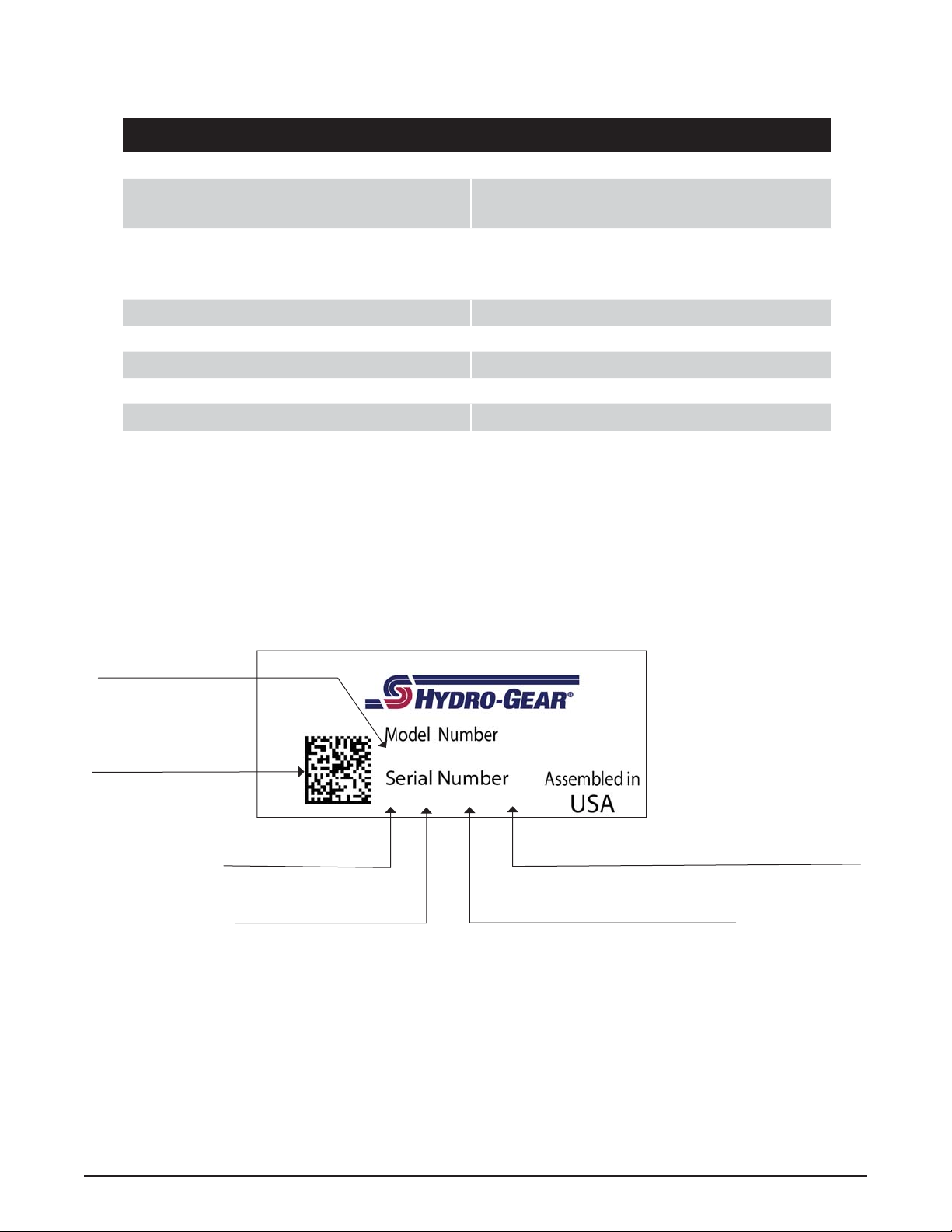
Figure 3, Product Label
1610-1001
2 275 X1 4761
2D Q Code
Year Built
Date (Julian - Day of Year) Type of Product and Build Information
Serial Number (unique for that model - for that day
BOM Model Number
PRODUCT IDENTIFICATION
The model and confi guration of the RT-310TM can be determined from the label found on the
transaxle.

6 RT-310TM
SAFETY
This symbol points out important safety
instructions which, if not followed, could endan-
ger the personal safety and/or property of your-
self and others. Read and follow all instructions
in this manual before attempting maintenance
on your hydraulic motor. When you see this
symbol - HEED ITS WARNING.
WARNING
POTENTIAL FOR SERIOUS INJURY
Inattention to proper safety, operation, or
maintenance procedures could result in
personal injury, or damage to the equip-
ment. Before servicing or repairing the
hydraulic motor, fully read and under-
stand the safety precautions described
in this section.
PERSONAL SAFETY
Certain safety precautions must be observed
while servicing or repairing the hydraulic motor.
This section addresses some of these precau-
tions but must not be considered an all-inclusive
source on safety information. This section is
to be used in conjunction with all other safety
material which may apply, such as:
1. Other manuals pertaining to this machine.
2. Local and shop safety rules and codes.
3. Governmental safety laws and regula-
tions.
Be sure that you know and understand the
equipment and the hazards associated with it.
Do not place speed above safety.
Notify your supervisor whenever you feel there
is any hazard involving the equipment or the
performance of your job.
Never allow untrained or unauthorized person-
nel to service or repair the equipment.
Wear appropriate clothing. Loose or hanging
clothing or jewelry can be hazardous. Use the
appropriate safety equipment, such as eye
and hearing protection, and safety-toe and
slip-proof shoes.
Never use compressed air to clean debris from
yourself or your clothing.
TOOL SAFETY
Use the proper tools and equipment for the
task.
Inspect each tool before use and replace any
tool that may be damaged or defective.
WORK AREA SAFETY
Keep the work area neat and orderly. Be sure
it is well lit, that extra tools are put away, trash
and refuse are in the proper containers, and dirt
or debris have been removed from the working
areas of the machine.
The fl oor should be clean and dry, and all ex-
tension cords or similar trip hazards should be
removed.
SERVICING SAFETY
Certain procedures may require the vehicle to be
disabled in order to prevent possible injury to the
servicing technician and/or bystanders.
The loss of hydrostatic drive line power may result
in the loss of hydrostatic braking capability.
Some cleaning solvents are fl ammable. Use only
approved cleaning materials: Do not use explo-
sive or fl ammable liquids to clean the equipment.
To avoid possible fi re, do not use cleaning sol-
vents in an area where a source of ignition may
be present.
“Discard used cleaning material in the ap-
propriate containers according to local, state,
and federal regulations.”

RT-310TM 7
TROUBLESHOOTING
In many cases, problems with a hydraulic sys-
tems are not related to a defective hydraulic
unit, but are caused by slipping drive belts,
partially engaged bypass valves, and loose or
damaged control linkages. Be sure to perform
all operational checks and adjustments outlined
in Service and Maintenance, before assuming
the hydraulic system is malfunctioning. The
table below provides a troubleshooting check-
list to help determine the cause of operational
problems.
WARNING
Do not attempt any servicing or ad-
justments with the engine running.
Use extreme caution while inspecting
the drive belt assembly and all vehicle
linkage!
Follow all safety procedures outlined in
the vehicle owner’s manual.
TROUBLESHOOTING CHECKLIST
Possible Cause Corrective Action
Unit Operates In One Direction Only
Control linkage bent or out of adjustment Repair or replace linkage on vehicle pump assembly
Drive belt slipping or pulley damaged Repair or replace belt/pulley on vehicle pump assembly
Vehicle Does Not Drive/Track Straight
Vehicle tires improperly infl ated Refer to vehicle manufacturer suggested tire pressure
Control linkage bent or out of adjustment Repair or replace linkage on vehicle pump assembly
Drive belt slipping or pulley damaged Repair or replace belt/pulley on vehicle pump assembly
Brake Partially Engaged Disengage Brake, Replace damaged brake components
Unit Is Noisy
Oil level low or contaminated oil Fill to proper level or change oil
Excessive loading Reduce vehicle loading
Loose parts Repair or replace loose parts
Air trapped in hydraulic system Purge hydraulic system
Brake Partially Engaged Disengage Brake, Replace damaged brake components
Unit Has No/Low Power
Engine speed low Adjust to correct setting
Control linkage bent or out of adjustment Repair or replace linkage on vehicle pump assembly
Drive belt slipping or pulley damaged Repair or replace belt/pulley on vehicle pump assembly
Oil level low or contaminated oil Fill reservoir to proper level or change oil
Excessive loading Reduce vehicle loading
Air trapped in hydraulic system Purge hydraulic system
Brake Partially Engaged Disengage Brake, Replace damaged brake components
Unit Is Operating Hot
Debris buildup around transaxle Clean off debris
Oil level low or contaminated oil Fill to proper level or change oil
Excessive loading Reduce vehicle loading
Air trapped in hydraulic system Purge hydraulic system
Brake Partially Engaged Disengage Brake, Replace broken, missing or frozen return spring
Transaxle Leaks Oil
Damaged seals, housing, or gaskets Replace damaged components
Air trapped in hydraulic system Purge hydraulic system
Table des matières
Autres manuels Hydro-Gear Système de microphone


Manuels Système de microphone populaires d'autres marques


Sennheiser
Sennheiser Evolution Wireless Digital EW-DX EM 2 Manuel utilisateur

Alpha Technologies
Alpha Technologies RBMS Manuel utilisateur

SWIT Electronics Co.,LTD.
SWIT Electronics Co.,LTD. CW-S150 Manuel utilisateur

Shure
Shure UA844 Manuel utilisateur

Panasonic
Panasonic SHFX70 - DVD HOME THEATER WIRELESS SYSTEM Manuel utilisateur

Pyle
Pyle PDWM5000 Manuel utilisateur