Hotblast 1551E Manuel utilisateur

United States Stove Company
227 Industrial Park Rd.
South Pittsburg, TN 37380 853125-0405H
Certied to: UL-391 (R2015) and Certied to: CSA
B266.1-11 (R2014)
U.S. ENVIRONMENTAL PROTECTION AGENCY
Certied to comply with the 2016 particulate
emission standards. Not approved for sale after
May 15, 2020
Report No. 0215WH055S.REV002
Wood Only Central Furnace
Owner’s Operation and Instruction Manual
MODEL: 1551E
SAVE THESE INSTRUCTIONS
THIS MANUAL WILL HELP YOU TO OBTAIN EFFICIENT, DEPENDABLE SERVICE FROM THE HEATER, AND ENABLE YOU
TO ORDER REPAIR PARTS CORRECTLY. KEEP IN A SAFE PLACE FOR FUTURE REFERENCE.
SAFETY NOTICE:
If this unit is not properly installed, a re may result.
For your safety, follow the installation instructions.
Never use make-shift compromises during the
installation of this unit. Contact local building or re
ofcials about permits, restrictions and installation
requirements in your area.
CAUTION!
Please read this entire manual before you install or
use this unit. Failure to follow instructions may result
in property damage, bodily injury, or even death.
Improper Installation Could Void Your Warranty!
CALIFORNIA PROPOSITION 65 WARNING:
This product can expose you to chemicals including carbon monoxide, which
is known to the State of California to cause cancer, birth defects and/or other
reproductive harm. For more information, go to www.P65warnings.ca.gov
Ce produit peut vous exposer à des produits chimiques, y compris le
monoxyde de carbone, qui est connu dans l'État de Californie pour causer
le cancer, des malformations congénitales et / ou d'autres problèmes de
reproduction. Pour plus d'informations, visitez www.P65warnings.ca.gov
-2-
CAUTION:
• Power source not controlled by furnace main disconnect.
• Respect all local and national codes when installing this unit.
• This unit is not to be connected to a chimney ue serving another appliance.
• This unit is designed to burn solid hardwood only.
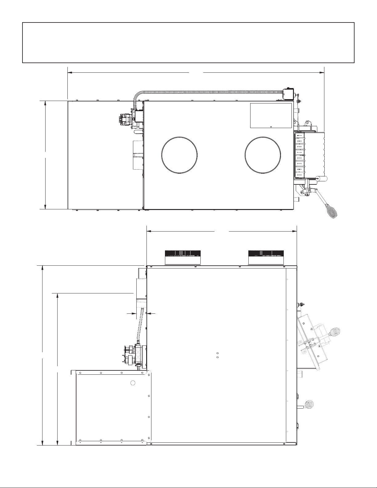
40
34
33.75
2.33
57.77
24.14

-3-
Specications
CONGRATULATIONS!
You’ve purchased a heater from North America’s oldest manufacturer of wood burning products.
By heating with wood you’re helping to CONSERVE ENERGY!
Wood is our only Renewable Energy Resource. Please do your part to preserve our wood supply. Plant at least
one tree each year. Future generations will thank you.
This manual describes the installation and operation of the Hotblast, 1551E wood heater. This heater meets
the 2016 U.S. Environmental Protection Agency’s emission limits for wood heaters sold after May 15, 2016. Under
specic EPA test conditions this heater has been shown to deliver heat at a rate of 18,850 – 56,000 BTU/hr. This
heater achieved a particulate emissions rate of 0.39 lb/mmBtu when tested to method CSA B415.1-10 (*and an
overall efciency of 62.6 %). The maximum overall heat output of this heater was tested to be 89,000 Btu/hr.
This wood heater has a manufacturer-set minimum low burn rate that must not be altered. It is against federal
regulations to alter this setting or otherwise operate this wood heater in a manner inconsistent with operating
instructions in this manual.
The operation of this wood heater in a manner inconsistent with the owner’s manual will void you warranty and
is also against federal regulations.
This heater is designed to burn natural wood only. Higher efciencies and lower emissions generally result when
burning air dried seasoned hardwoods, as compared to softwoods or to green or freshly cut hardwoods.
This wood heater needs periodic inspection and repair for proper operation. It is against federal regulations to
operate this wood heater in a manner inconsistent with operating instructions in this manual.
Combustible: Wood
Flue Pipe Diameter: 6” (153cm)
Flue Pipe Type: (Standard,
Single Wall, or Double Wall): Black or Blued Steel 2100°F (650°C) Class “A”
Minimum Chimney Height: 12’
Maximum Log Length: 27”
Electrical: 120V, 60Hz, 2.6A per blower (5.2A on start up for both blowers)
Dimensions
Combustion Chamber:
Width x Depth: 17.4” X 28.3”
Volume:
Cubic Feet: 5.2 cubic feet
Door Opening: Width x Height: 11.6” X 11.5”
Weight (lbs): 509 lbs.

-4-
Safety
• WARNING: Do not operate with fuel loading or ash removal doors open.
• Do not connect this unit to a chimney ue serving another appliance.
• WARNING DANGER: Risk of re or explosion. Do not burn garbage, gasoline, naphtha, motor oil, or other
inappropriate materials. Do not use chemicals or uids to start the re.
• WARNING: Risk of re. Do not operate with ue draft exceeding .060” water column/14.93 Pascals. Do not
operate with fuel loading and ash removal doors open. Do not store fuel or other combustible materials
within marked installation clearances. Inspect and clean ues and chimney regularly.
• CAUTION: Hot surfaces. Keep children away. Do not touch during operation.
• The heat exchanger, ue pipe, and chimney must be cleaned regularly to remove accumulated creosote
and ash. Ensure that the heat exchanger, ue pipe, and chimney are cleaned at the end of the heating
season to minimize corrosion during the summer months. The appliance, ue pipe, and chimney must be
kept in good condition. These instructions also apply to a draft inducer if used. To prevent ame or smoke
spillage, the slide bafe must be pulled out and the fuel loading door left cracked for 10 seconds prior to
opening door fully. Load fuel carefully or damage may result.
• Hot while in operation. Keep children, clothing and furniture away. Contact may cause skin burns.
• Do not use chemicals or uids to ignite the re.
• Do not leave the furnace unattended when the door is slightly opened.
• Do not burn garbage, ammable uid such as gasoline, naphtha or motor oil.
• Always close the door after the ignition.
• Consult your municipal building department or re ofcials about permits, restrictions and installations
requirements in your area.
• INSPECT FLUE PIPES, FLUE PIPE JOINTS, AND FLUE PIPE SEALS REGULARLY TO ENSURE THAT SMOKE AND FLUE
GASES ARE NOT DRAWN INTO, AND CIRCULATED BY, THE AIR-CIRCULATION SYSTEM.
• CAUTION: CLEAN OUT OF THE HEAT EXCHANGER, FLUE PIPE CHIMNEY, AND DRAFT INDUCER, IF USED, IS
ESPECIALLY IMPORTANT AT THE END OF THE HEATING SEASON TO MINIMIZE CORROSION DURING THE SUMMER
MONTHS, CAUSED BY ACCUMULATED ASH.
Unpacking And Preassemble
UNPACKING
1. Remove all packaging from the furnace.
2. Remove the supplied parts from the furnace.
BRICK ALIGNMENT
Inspect for any damage. Ensure that the bricks and ash plug are positioned correctly and not broken (see
illustration for proper brick arrangement).
TOOLS AND MATERIALS NEEDED FOR INSTALLATION
The following is a list of tools and materials needed to install
your furnace.
• 7/16” socket wrench.
• 5/16” socket (Best if using a power drill and a socket bit).
• Pair of pliers or channel-locks.
• Power drill with an 1/8” drill bit to install sheet metal screws
into connector pipe..
• Sheet metal screws.
• Non-combustible oor protector as specied in this
manual.
• All chimney and chimney connector components
required for your particular venting installation..
• Electrical wiring tools and supplies.
• Ductwork for supply and return air.
Proper Fire Brick Alignment

-5-
Furnace Installation
Dimension Inch mm
A Backwall to Furnace 28 712
BSidewall to Furnace 16 407
CSidewall to Flue 25 635
DBackwall to Flue 18 458
ESupply Duct (rst 6 feet) 6 153
F Supply Duct (after rst 6 feet) 1 26
G Minimum Duct height 8 204
H Top of Door to Ceiling 48 1220
JMinimum Ceiling Height 77 1956
INSTALLATION OPTIONS
The installation of this furnace includes supplying electrical power, return (fresh air) ductwork, and supply air
ductwork. This furnace may be installed in two different congurations.
1. Stand alone wood furnace
2. Add-on wood furnace
See kit installation section in this manual to ensure proper assembly, installation and operation of your new
furnace.
If installing in an area with a fan it should not be allowed to create negative pressure in the room where the
furnace is installed.
LOCATING YOUR FURNACE (INSURE THAT THE REQUIRED MAINTENANCE CLEARANCES ARE MAINTAINED)
Your furnace must be installed as shown in this manual and in compliance with all local and national codes.
It is of the utmost importance that the clearances to combustible materials be strictly adhered to during
installation of the furnace. Refer to the table and diagrams below for minimum required clearances.
CLEARANCE TO COMBUSTIBLESCLEARANCE TO COMBUSTIBLES
Back wall
Side wall
Side wall
C
B
A
Ceiling
Floor Protector
E
F
G
H
J
D

-6-
MAINTENANCE CLEARANCES
Your furnace has recommended minimum maintenance clearance
requirements. These clearances insure that there is adequate room to preform
maintenance and service your furnace. DO NOT store fuel within the specied
clearances. See the table and diagram below to determine the clearances
for your furnace.
Dimension Inch mm
K Maintenance Clearance (Front) 24 610
L Maintenance Clearance (Left) 24 610
MMaintenance Clearance (Right) 24 610
NMaintenance Clearance (Rear) 36 915
FLOOR PROTECTOR REQUIREMENTS
FLOOR PROTECTOR
The furnace must be placed on solid concrete, solid masonry, or when
installed on a combustible oor, on a oor protector. The oor protector is
required to provide heat, live ember, and ash protection and must be of a
non-combustible, continuous solid surface to protect against inltration of
live embers and ash. Floor protection must have and R-Value of at least 2.8.
Refer to oor protector manufacturer’s instructions for installation directions.
The oor protector or non combustible oor must extend under the furnace
and beyond each side as shown below.
Dimension Inch mm
O* Front 16 407
PFlue rear 2 51
Q** Left 8 204
R** Right 8 204
SFlue Side 2 51
Duct Work Installation
We strongly recommend that the hot air ductwork be installed by a home
heating specialist. If doing the installation yourself, before you decide
which installation will best suit your needs, consult a qualied heating
technician and follow his recommendations as to the safest and most
efcient method of installation. This furnace can be installed in three ways,
as a stand alone unit, parallel, and in series with an existing furnace.
SUPPLY AIR (HOT AIR) PLENUM
The warm-air supply duct shall be constructed of metal in accordance with
NFPA 90B, 2-1.1. The plenums installed to the furnace shall be constructed
of metal in accordance with NFPA 90B, 2-1.3. When installing this furnace
the hot air plenum is to have a minimum height of 24” (610mm) if the top
of the rst vertical section is not ush with the top of the rst horizontal
section of ductwork. If the top of the plenum is ush with the top of the
rst horizontal section of ductwork then the minium height is 15” (381mm).
RETURN AIR (FRESH AIR)
The return (fresh) air intake on the furnace is on the rear of the unit. The
ductwork must be mechanically attached to the unit or UFB908 blower
box with sheet metal screws to ensure a proper operation.
STAND ALONE INSTALLATION
If installing this furnace as a stand alone unit, ensure all local codes
and all instructions in this manual are followed, including clearance to
combustibles, oor protector specications and safety warnings.
6” 24 1/16”
Supply Air (Hot Air) Duct Work Outlet Size
Supply Air Plenum
Minimum Height Of 24”
Supply Air Plenum With
Minimum Height Of 15”
MAINTENANCE CLEARANCE
ML
N
K
Q
O
R
P
SS

-7-
CENTRAL INSTALLATION
Central Installation
ASSEMBLY OF FURNACE
Your furnace requires the following items to be
assembled or installed by the service person:
Blowers and Blower Controls
Electrical Connections
1. Remove all parts from the unit (blowers,
thermodisc, and all wiring) and inspect for
damage, including the rebrick as some
breakage could occur during shipment.
2. Install the thermodisc on rear of furnace
cabinet with the two screws provided.
Mount the conduit assembly from the
junction box to the thermostat bracket.
Crimp the two female terminals to each
of the wire leads. Plug the wires to the
thermodisc. NOTE: It does not matter which
of the two wires plugs to which terminal on
the thermodisc.
3. Remove blowers from cartons. Remove
junction box cover. Attach clip nuts as in
gure shown. Install blower(s) and gasket(s
with 1/4"-20 x 3/4" bolts as shown.
4. Wire right side blower rst (See wiring
diagram) and replace cover on junction
box on blower.
5. Wire left blower same as above and
replace cover.
Accessory Installation
THERMODISC
THERMODISC
COVER
4” ELECTRICAL
JUNCTION BOX
BLOWERS
BLOWERS GASKET CLIP NUTS
(Not used in the upper center hole.)

-8-
SMOKE CURTAIN
Using two 1/4-20 x 1-1/4” Carriage bolts, two smoke curtain clips, and two nuts, attach the smoke curtain in
place above the fuel feed door as shown. After installation, the smoke curtain should swing freely back into the
furnace.
DOOR LATCH INSTALLATION
Use the two included bolts and nuts to secure the handle to the stove as shown.
Note: Adjust the handle as needed to insure a proper seal.
HEAT SHIELD INSTALLATION

-9-
Electrical Installation
All electrical connections should be done by a qualied electrician
It is recommended to connect the furnace to its own 15 amp 120 Volt circuit from the house power supply
105°C
NOTE: Wire leads from the distribution blower are usually
BOTH BLACK. Makes no difference which leads from the
motor(s) connects to the corresponding leads coming out of
the conduit.

-10-
STEP 1
Slide the motorized draft actuator into the servo
bracket as shown.
STEP 2
Secure the motorized draft actuator to the servo
bracket using (1) one #10 X 1/2 screw.
STEP 3
Place (1) one 1/4-20 X 3/4 bolt into the servo arm and
secure with (1) one washer and (1) one 1/4-20 lock nut
as shown. Insert the servo arm into the actuator.
STEP 4
Attach the actuator to the unit by inserting (2) two 10-
24 X 1/2 screws into the pre-drilled holes located on
the upper right side of the unit. NOTE: The actuator will
need to be mounted ush against the stove. Insure the
actuator is mounted ush by removing the panel screw
before mounting the actuator.
15MDK Thermostatically Controlled Damper Installation
*CANADIAN RESIDENTS ARE REQUIRED TO USE THIS KIT FOR INSTALLATION.
Servo Arm Actuator
853252
Table des matières
Autres manuels Hotblast Four

Hotblast
Hotblast 1300 Manuel utilisateur

Hotblast
Hotblast 1300 Manuel utilisateur

Hotblast
Hotblast HB1330E Manuel utilisateur

Hotblast
Hotblast 1300 Manuel utilisateur

Hotblast
Hotblast HB1440E Manuel utilisateur

Hotblast
Hotblast 1300 Manuel utilisateur

Hotblast
Hotblast 1357M Manuel utilisateur

Hotblast
Hotblast 1400E Guide de démarrage rapide


