Horstmann CentaurPlus ZW Manuel utilisateur

CentaurPlus ZW and HRT4-ZW
Installation Instructions
The Horstmann CentaurPlus ZW combined wireless room stat and timeswitch
allows a combi boiler system to have a room thermostat added without the
needforanyadditionalwiring.
ReplacingtheexistingtimeswitchwiththeCentaurPlusZWwillallowtheroom
thermostat to be connected wirelessly producing immediate energy savings in
houseswherenopreviousroomthermostathasbeenfitted.
The device is intended to upgrade existing combi boiler systems that do not
havean existingroomthermostat. Itisnot intendedfornew installationswhere
it will be necessary to install two heating zones in order to comply with current
BuildingRegulations.
1

For the installer
Installation and connection should only be carried out by a suitably qualified person
and in accordance with the current edition of the IEE wiring regulations.
WARNING: Isolate mains supply before commencing installation.
An example circuit diagram for a typical combi boiler installation is shown below. This
diagram is schematic and should be used for guidance only.
N
N
E
L
L 1 2 3 4
For precise terminal
connection information
please refer to boiler
manufacturer's instructions REMOVE LINK
IF REQUIRED
TERMINALS L-2
SHOULD NOT
BE LINKED
BOILER LIVE OUT
SWITCHED LIVE
RETURN TO BOILER
MAINS
SUPPLY
ENL
COMBINATION BOILER TERMINALS
Wireless link
CentaurPlus ZW
ROOM
STAT
2

Fitting the backplate
Once the backplate has been removed from the packaging please ensure the
timeswitch is re-sealed to prevent damage from dust, debris.
The backplate should be fitted with the wiring terminals located at the top and in a
position that allows a total clearance of at least 50mm around the unit.
Direct wall mounting
Offer the backplate to the wall in the position where the timeswitch is to be mounted,
remembering that the backplate fits to the left hand end of the control. Mark the fixing
positions through the slots on the backplate (fixing centres of 60.3mm), drill and plug
the wall, then secure the plate in position. The slots in the backplate will compensate
for any misalignments of the fixings.
Wiring box mounting
The backplate may be fitted directly onto a single gang steel flush wiring box
complying with BS4662, using two M3.5 screws. CentaurPlus controls are suitable for
mounting on a flat surface only; they must not be positioned on a surface mounted wall
box or on unearthed metal surfaces.
3

1
2
4
1 - RATINGS LABEL
2 - BATTERY
3 - CONNECTOR PINS
4 - PRODUCTION DATE LABEL
L1 2 3
230V 50 Hz COMM OFF
4N
ON
Electrical Connections
Allnecessaryelectricalconnectionsshouldnowbemade.Flushwiring can enter from the
rearthroughtheapertureinthebackplate.Surfacewiringcanonlyenterfrombeneaththe
timeswitchandmustbesecurelyclamped.Recommendedcablesizesare1.00or1.5mm.
CentaurPlus timers are double insulted and do not require an earth connection but an
earthconnection is providedonthe backplate forterminating any cable earthconnectors.
Earth continuity must be maintained and all bare earth connectors must be sleeved.
Ensure no earth conductors are left protruding outside the central space enclosed by the
backplate.
Internal diagram - C17 -ZW
The CentaurPlus ZW has voltage free
contacts. A link L-2 is required for mains
voltage applications
Battery reserve
The battery must be commissioned prior to fitting the timeswitch to the backplate. This
is achieved by the means of a commissioning strip situated in the back of the unit. Pull
out the battery commissioning strip at the back of the timeswitch and re-insert the
battery; the reserve is now activated. When the timeswitch is running the battery
reserve clock display will disappear. This is to prolong the life of the battery.
PULL TO REMOVE
3
Rear view of CentaurPlus timeswitch
4

SET
SELECT
Fitting the timeswitch
EndviewofCentaurPlustimer
If surface wiring has been used, remove the knockout/insert from the bottom of the
timeswitchtoaccommodateit.
Loosen the two ‘captive’ retaining screws on the bottom of the backplate. Now fit the
timeswitch to the backplate, ensuring the lugs on the backplate engage with the switch.
Swing the bottom of the timeswitch into position ensuring that the connection pins on the
backoftheunitlocateintotheterminalslotsinthebackplate.
Tightenthetwocaptiveretainingscrewstofixtheunitsecurely.
Thenswitchonthemainssupply.
Oncompletionoftheinstallationpleaseresetthetimeswitchasdetailednext;
Resetting the timeswitch
On the CentaurPlus press the SET and SELECT buttons together. Then release the
buttons and the timer will return to preset factory settings The preset factory settings
are illustrated on page 10 of the USER GUIDE. The time and date will also be reset
and need to be re-entered.
The unit is now ready to be signed on to its HRT4-ZW room thermostat, to suit the
user’s requirements
5

GeneralInformation
BATTERY
The timeswitch is fitted with a non-rechargeable, long life battery, which will maintain the
programmedtimesettingsforaminimumoftenmonthswiththesupplydisconnected.
THIS SHOULD BE SUFFICIENT TO COVER POWER INTERRUPTIONS DURING THE
LIFEOFTHEUNIT.
Duringpowerinterruptionsthedisplaywillbeblank,after3daysthecurrenttimeofdaywill
belost.Thesemeasuresaretoprolongthebatterylife.
SERVICEANDREPAIR
ThistimeswitchisNOTuserserviceable.Pleasedonotdismantletheunit.
In the unlikely event of a fault developing please refer to the RESETTING THE
TIMESWITCHsectionofthis user guide.Ifthisfailstoresolvethe problem pleasecontact
yourinstaller,alocalheatingengineeroraqualifiedelectrician.
6

Installationandpairinginstructions
HRT-4ZW room thermostat
The HRT4-ZW is a wireless electronic battery powered room thermostat that uses
interoperable two-way RF mesh networking technology to provide optimum comfort with
closecontrol of theenergy used toheatthe home withoutthe need foradditionalwiring or
unsightlycableruns.
The HRT4-ZW will only operate when 2 x AAA batteries have been fitted and the
thermostatisinstalledandcommunicatingwiththeCentaurPlusZWtimer/receiverunit.
INSTALLATION AND CONNECTION OF THE HRT4-ZW SHOULD ONLY BE CARRIED
OUTBYASUITABLYQUALIFIEDPERSON.
7

Stage1
1)Setthe number 1DILswitch on thebackof the HRT4-ZW
thermostat to the On (Up) position and the display will
changetoshowtheletter‘I’.Iftheletter‘L’appears,carryout
stage1Aopposite.
2)PoweruptheCentaurPlusZWtimeswitch.
3) Press the dial on the front of the HRT4-ZW thermostat
oncesothatthe‘I’inthedisplayflashes.
4) Press and hold the ‘Boost’and ‘Enter’ buttons on
the front of the CentaurPlus ZW until an indicator
appears in its display against the radio aerial
symbol.
5) After a few seconds the radio mast symbol
willappearinthedisplayalongwiththelettersIP.
6) Reset the number 1 DIL switch on the back of
the HRT4-ZW to the Off position and the
temperaturewillappearinthedisplay.
7)NowchecktheCentaurPlusZWtimecontrolisreceivingsignalsfromthethermostat
byturningthetime switchtoan‘On’settingwiththeredindicator lightlitandturningthe
thermostatupanddowntomaketheboilerswitchonandoff.
N.B. There is a half second delay in switching On and Off on receipt of the
commands. There is no ‘click’ from the thermostat which is silent in operation but
there will be an audible ‘click’ from the CentaurPlus ZW when it is ‘On’and the
thermostat switches On and Off.
8)Whenthethermostatiscallingforheataflamesymbolwillappearinitsdisplay.
9)ZWavecommunicationisnowsuccessfullyestablished.
Instructions for pairing the HRT4-ZW room thermostat
withtheCentaurPlusZW
These devices use the latest Z-Wave wireless communication technology to give a
reliable wireless link that should not suffer from interference from other nearby devices.
The device comprises a thermostat (the HRT4-ZW) and its receiver (the CentaurPlus
C17-ZW).Pairingthedevicesonsiteensuresreliablecommunication.
Follow these steps to ensure that the HRT4-ZW thermostat will communicate
satisfactorilywith itsreceiver.Thisisbestcarriedout withtheHRT4-ZWthermostat
heldnearbythe(powered)CentaurPlusC17-ZW.
Press and hold ‘BOOST’ and ‘ENTER’buttons to
‘SIGN ON’ or ‘PAIR’ the HRT4 ZW thermostat
8
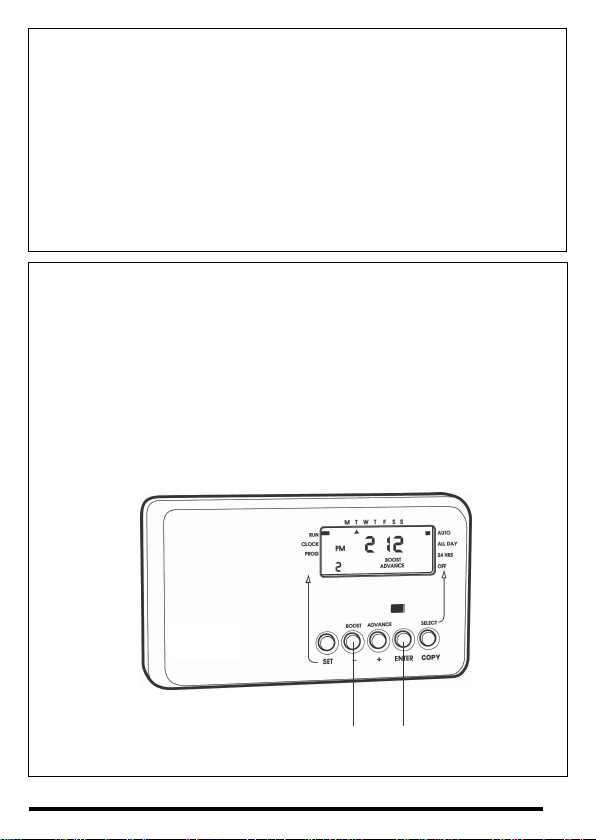
Press and hold 'BOOST' and 'ENTER' buttons to 'SIGN ON or 'PAIR' the HRT4-ZW thermostat.
Stage1A-only usedif ‘L’isdisplayedinsteadof‘I’
1)TurnthedialoftheHRT4-ZWuntiltheletterPappearsinthedisplay.
2)PressthedialtwiceandPPshouldappearinthedisplay.
3) Turn the dial until the letter ‘I’ appears in the display and return to the main
instruction.
Under normal circumstances the HRT4-ZW thermostat and CentaurPlus C17 ZW will
be ‘paired’ easily by following the procedure shown under Stage 1 of the pairing
instructions.
Only use Stage 2 if a radio link cannot be successfully established between the two
devices.
Stage 2 - only used if above procedure does not establish a successful
communicationlink
1)TurnthedialoftheHRT4-ZWuntiltheletterPappearsinthedisplay.
2)PressthedialtwiceandPPshouldappearinthedisplay.
3)NowturnthedialuntilletterEappearsinthedisplay.
4)Pressthedialonceandthedisplayshouldflash‘E’.
5)Pressandholdthe‘Boost’and‘Enter’buttonsontheCentaurPlusZW.
6) Turn the thermostat dial until ‘I’ appears in the display and return to the main
instruction.
9

DILswitchsettings-TPItemperaturecontrolsoftware
Thermostats using TPI (Time Proportional Integral) control algorithms will reduce the
temperature swing that normally occurs when using traditional bellows or thermally
operated thermostats.As a consequence, a TPI regulating thermostat will maintain the
comfortlevelfarmoreefficientlythananytraditionalthermostat.
When used with a condensing boiler, the TPI thermostat will help to save energy as the
control algorithm allows the boiler to operate in condensing mode more consistently
comparedtooldertypesofthermostat.
ŸDILswitchnumbers7and8shouldbesetasdiagramopposite.
ŸForGasboilerssettheTPIsettingto6cyclesperhour(Defaultsetting)
ŸForOilboilerssettheTPIsettingto3cyclesperhour.
ŸForElectricheatingsettheTPIsettingto12cyclesperhour.
10
Ce manuel convient aux modèles suivants
1
Table des matières


