Hix PREMIER CONVERTIBLE Series Manuel utilisateur

Printer/ Assembly 2-4
Set Printhead 5
Screen Installation & Adjustment 6
PrePress and Registering 7-11
Gas Spring Replacement 12-13
HIX Manual Printers 14-15
Warranty 16
HIX PREMIER PRINTERS
CONVERTIBLE/RALLY/CRUISE/GT SERIES
OWNER’S MANUAL
CONTENTS
BEFORE warranty repair you MUST get Prior Authorization:
Manual Screen Printer
For Customer Service, Call 1-800-835-0606
or Visit www.hixcorp.com
6 Color / 4 Station
CRUISE model shown
70663 RV D_120820

2
PRINTER ASSEMBLY
TOOLS REQUIRED:
(2) 9/16” Wrench
(2) 1/2” Wrench
(1) 7/8“ Socket and Ratchet
(1) Phillips Screwdriver
Assembly (if press is assembled/ partially assembled go to next step)
ARM ASSEMBLY
1. Slide each arm under the ange nut on lower print wheel, and then
tighten from the bottom.
2. Insert the additional (2) 1/2” bolts (Fig 1) to print arm anges and
tighten.
BASE ASSEMBLY
Empty the contents of ALL cartons on the oor.
NOTE:This will require two people.
1. Place leg assembly on oor, leveling pads down.
2. Align base with (4) holes on leg assembly. (2 people re quired)
3. Tighten the (4) 3/8” bolts down to leg assembly with 9/16” wrench.
4. To level printer adjust leveling pads and tighten jam nuts.
Fig 1
Fig 2
PRINT HEAD ASSEMBLY
1. Remove the nut, bearing cap cardboard
tube and plastic shrinkwrap from spindle
(Fig 2).
2. Remove the top bearing from spindle and
set on a clean cloth.
3. Place print head wheel assembly over
spindle.

3
PRINTER ASSEMBLY
NOTE: Make sure the bearing is seated evenly in the bearing race on the
bottom of the printwheel assembly such that wheel assembly turns
freely. 2 people required (Fig 3).
4. Place the tapered end of the bearing into the top race
of the printwheel assembly and hand tighten the cap
on screw until snug. The cap on screw can then be
tightened an additional ¼ turn by inserting a rod into
the hole in the top of the bearing cap. (Fig 4)
SHIRTBOARD POSITION
5. Holding the bearing cap in place, tighten the nut rmly on the top of
the spindle assembly.
NOTE: Spin and gently rock both upper and lower printwheels to assure
bearings are seated properly (Fig 5).
Attach shirtboards on the print arms, at
side in, push the shirtboard to the back
until they rest just under the print head and
tighten them using the knobs located on
the side FIRST. Tighten the bottom knob
second on the shirtboard clamps (Fig 6).
Fig 3
Fig 5
Fig 6
Fig 4

4
PRINTER ASSEMBLY
REGISTRATION GUIDE ALIGNMENT
1. Lower all print heads (Fig. 7). Tighten the (2) bolts (Fig. 8) that secure
the registration guide bracket to the arm.
NOTE: This procedure must be done to ensure all print heads will register
for printing.
BRAKE WHEEL ADJUSTMENT
1. The brake wheel is mounted so as to allow the wheel to be raised or
lowered to provide the braking action desired.
2. Loosen the retaining bolt and align brake wheel under a print arm.
3. Insert a Phillips screwdriver into the hole on the brake wheel shaft.
(Fig. 9)
4. Raise or lower the brake wheel by moving the screwdriver to the desired
brake resistance (Fig. 9).
5. Tighten the retaining bolt and check the braking action.
6. Re-adjust if needed.
Print Heads Down
Fig. 7
Two Bolts
Fig. 8
Fig. 9

5
SET PRINTHEAD
YOUR HIX PRESS MUST BE REGISTERED ON CONTACT!
(Meaning the exposed screen is touching the shirtboard. )
1. Front to rear adjustment. Insert Screen into screen clamp (see
page 6) and adjust the screen tilt adjustment (see page 9).
Adjust so that the screen is parallel with the shirt board front to back,
and make sure your screen sits totally at on the shirtboard. Or the
screen will slip when you tighten the ratchet handles. (See handles on
page 7 Fig. 13)
2. Left to right/ Parallel adjustment. Be sure the back screen clamp (or
cross tube holding side clamps) is level and parallel in relationship to
the shirtboard. (Left to right on the shirtboard) There are two bolts that
secure the back clamp (or crosstube) to the lower registration plate.
Slightly loosen nuts holding these bolts. The left side of the back
clamp (or crosstube) is oversized which allows you to move the clamp
(or crosstube) to align the screen parallel to the shirt board. Adjust to
parallel and tighten.
NOTE: If not level after tightening repeat steps 1 and 2 above.
WARNING: Failing to level this section of the printer will cause an un-even
contact from the left to the right or front to rear. This may
will cause the screen to “slip” or move when you tighten the
registration ratchet handles.
NOTICE: Failing to properly set up
printhead level will not allow
print to be registered.
Back clamp Cross tube that holds side clamps
Shirtboard
Screen Level
Screen not level
Front to Rear
Left to Right
Shirtboard
Not to scale

6
SCREEN INSTALL. & ADJUST.
FOR BACK CLAMPS: (FIG. 10)
1. 1. Loosen both black knobs on the back clamp and center the screen
in the clamp making sure the screen is all the way inside the clamp.
2. 2. Tighten the black knobs so that they securely grip the screen.
FOR SIDE CLAMPS: (FIG. 11 AND 12)
(If the side clamp is not attached see Fig 12)
1. Loosen the two black adjustment knobs on each side clamp wide
enough to accept the screen.
2. Loosen the angled back knob on the back of each side clamp and
move clamps far enough apart on the cross tube so that the screen
will t into the clamps.
3. Insert the screen into the side clamps and press clamps inward so that
they are against the sides of the screen frame and centered over the
shirtboard. Center on the crosstube.
4. Gently tighten the angled knobs on the cross tube.
NOTE: Do not overtighten.
5. Tighten the two black knobs on each side clamp to securely grip the
screen.
Side Clamp Fig. 11
Back Clamp Fig. 10
Fig. 12
Slide this
side over
cross tube.
NOTE: The bolt securing the left hand side of the cross tube is in an over-
sized hole allowing for adjustment if a screen is slightly warped
or twisted. Likewise, printers congured with the back clamp fea-
ture a similar slotted hole which exists to allow for leveling of the
screen.
Remember if you modify this adjustment for a warped screen, to
reset printhead for at screen (see page 5)
Loosen the nuts on the cross tube or the back clamp. Adjust up or
down so that the screen is parallel (right to left) to the shirt board.

7
PREPRESS & REGISTRATION
NOTICE: Before printing follow these steps below.
1. The rst step involves setting all
micro register heads to a neutral
position. This can be done by
loosening the ratchet handles ap-
proximately a 1/4 turn (Fig. 13) and
then turning the three registration
knobs (Fig. 14) until the arrow tab
points (Fig. 15) to the center of the
inscribed cross hairs.
Perform this adjustment on every
print head that takes a screen.
Fig. 14
Fig. 13
registration
knobs
ratchet handles
Fig. 15

8
PREPRESS & REGISTRATION
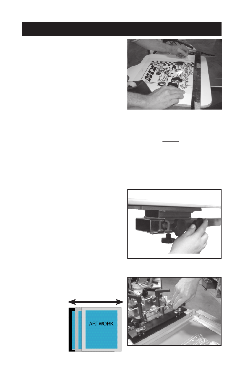
2. Center, level, and tape your art/
lm positive (normally the black
or trap) on one shirt board using
a T-Square and a ruler. Roughly
center or position to desired lo-
cation. Make sure all printable
images lie within the bound-
ary of the shirtboard. (Fig. 16)
Then register your screens to
the film positive (see page 9).
(film positive- Any artwork on
a clear lm that can be used to
expose a screen.
3. Optionally, if you do not have a positive or vellum; you can spray tack
adhesive on the shirt board, then load a shirt or pellon onto the board.
Then “print” the black/darkest color or keyline positive directly onto the
shirt or pellon. Cure, then register your screens to this print (see page
9). (keyline positive- the outline that traps all other color separation
positives. pellon- test print material, so to not ruin usable material.)
NOTE: Slight adjustments to the shirtboard to improve alignment may be
necessary.
4. To adjust the shirtboard: (Fig.
17) Loosen the shirt board and
position so that it lines up with the
screen frame when it is lowered
into the horizontal position.
REMEMBER to tighten the side knob
rst and then the bottom/larger knob.
5. Lower the screen onto the shirt
board with the taped artwork.
6. Loosen the screen clamps on back
clamp models or angled back
knob on side clamp presses and
center the screens side to side if
needed.
Fig. 16
Fig. 17
Fig. 18
Note: Keep
in mind you
still want the
screen to fit
tight against
the back of the
screen clamps
to improve sup-
port. (Fig. 18)
side to side

9
PREPRESS & REGISTRATION
7. Lower your screen all the way down to the shirt board. You may have
to use the o contact adjustor (Fig. 19) and your screen leveler (Fig.
20) to achieve front to rear “contact” with the shirt board. Now slightly
loosen the ratchet handles. You should be able to notice the movement
of the screen after adjusting the three adjustment nuts. (Fig. 14)
If not parallel left to right see page 5, step #2.
8. Looking through the screen (Fig. 21) use the adjustment knobs. (Fig. 22-23)
Once you have achieve perfect lineup with the screen and art, hold the
screen down with your hand and then working back and forth, gently
snug up the ratchet handles (Fig. 23) until the screen is rmly locked
in place. Recheck your registration then use the o contact and the
screen leveling adjustment to raise the screen approximately 1/16” o
the shirtboard surface.
NOTE: If your ratchet handles are too tight you may cause damage to the
adjustment nuts by forcing them. (Fig. 23)
Fig. 19
o contact adjustor screen leveler
Fig. 20
ShirtboardShirtboard
Fig. 21 Fig. 22

10
PREPRESS & REGISTRATION
If your clamps are too loose when you begin the adjustments (Fig.
23) your screen may jump out of registration during nal clamping.
(See page 5)
Fig. 23
ratchet handles
registration
knobs
9. Before proceeding to the next print head alignment, measure the dis-
tance between the end of the shirt board clamp and the registration
guide on the print arm. This distance should be the same for all the
other shirt boards in the setup process. (Fig. 24) Adjust if necessary
see shirtboard position pg. 3
NOTE: Over time the bushings (Fig. 25) between the micro-registration and
the H-Arm could become worn and create play in the print head.
This play can cause prints to fall out of registration. An adjustment
to the registration take-up nut (Fig. 26) on the micro-registration
will need to be made.
Fig. 24
Fig. 25
Fig. 26
H-Arm
Ce manuel convient aux modèles suivants
3
Autres manuels Hix Imprimante


