Hi-Link HLK-B35 Manuel utilisateur

Shenzhen Hi-Link Electronic Co., Ltd.
HLK-B35 User Manual
Version:V1.0 Revise date:2020 年 11 月 19 日 Reserved ©Shenzhen Hi-Link Electronic Co., Ltd

1
目CONTENTS
1. PRODUCT INTRODUCTION........................................................................................................................................ 1
1.1. BRIEF INTRODUCTION........................................................................................................................................ 1
1.2. PRODUCT FEATURES............................................................................................................................................ 1
1.3. PERFORMANCE AND ELECTRICAL PARAMETERS.................................................................................................. 2
1.4. PRODUCT PACKAGE SIZE AND PIN DEFINITION.............................................................................................. 4
1.5. PIN INTRODUCTION............................................................................................................................................ 4
1.6. SYSTEM BLOCK DIAGRAM.................................................................................................................................... 6
1.7. TEST BOARD INTRODUCTION.............................................................................................................................. 6
2. FUNCTION DESCRIPTION........................................................................................................................................ 7
2.1. WIFI INDICATOR FLASHING DESCRIPTION...................................................................................................... 7
2.2. UART TO WIFI STA............................................................................................................................................ 7
2.3. UART TO WIFI AP.............................................................................................................................................. 8
2.4. SERIAL PORT WORKING STATUS CONVERSION.................................................................................................. 8
2.5. SERIAL-TO-NETWORK DATA CONVERSION.......................................................................................................... 9
2.5.1. MODULE AS TCP SERVER................................................................................................................................ 9
2.5.2. MODULE AS TCP CLIENT................................................................................................................................ 9
2.5.3. MODULE AS UDP SERVER.............................................................................................................................. 10
2.5.4. MODULE AS UDP CLIENT.............................................................................................................................. 10
3. AT COMMAND INSTRUCTIONS................................................................................................................................ 10
3.1. BASIC AT COMMANDS........................................................................................................................................ 11
3.2. WI-FI RELATED AT COMMANDS........................................................................................................................ 14
3.3. TCP/IP RELATED AT COMMANDS...................................................................................................................... 15
3.4. BLE RELATED AT COMMANDS............................................................................................................................ 18
3.5. CUSTOM MESSAGE PROMPT INSTRUCTION........................................................................................................ 18
4.AT COMMAND CONTROL CODE EXAMPLE.................................................................................................................. 20

4.1. QUERY CONFIGURATION INFORMATION............................................................................................................ 20
4.2. CONFIGURE THE MODULE AS A CLIENT (STATIC IP ADDRESS)..................................................................20
4.3. CONFIGURE THE MODULE AS A SERVER (DYNAMIC IP ADDRESS)................................................................22
4.4. RESET.................................................................................................................................................................23
5. BLUETOOTH DISTRIBUTION NETWORK AND DATA TRANSPARENT TRANSMISSION..............................................24
5.1. BLUETOOTH DISTRIBUTION NETWORK.............................................................................................................. 24
5.2. BLUETOOTH TRANSPARENT TRANSMISSION...................................................................................................... 24
6. MODULE POWER CONSUMPTION MEASURED DATA.................................................................................................. 25
6.1. POWER CONSUMPTION IN STA MODE................................................................................................................ 25
6.2. POWER CONSUMPTION OF TRANSPARENT DATA TRANSMISSION IN STA MODE..............................................26
6.3. POWER CONSUMPTION IN AP MODE.................................................................................................................. 26
7. APPENDIX A DOCUMENT REVISION HISTORY...................................................................................................... 27

User Manual
第1页共30
HLK-B35
1. Product Introduction
1.1. Brief introduction
HLK-B35 is a low-cost embedded UART-WIFI (serial-wireless network) module launched by
Hi-link Electronics. It is a Wi-Fi + BLE combined chipset for low-power and high-performance
application development.
This product is based on an embedded module that conforms to network standards through a
serial interface, with an embedded TCP/IP protocol stack, which can realize the conversion between
the user's serial port and the wireless network (WIFI/BLE).
With the HLK-B35 module, the traditional serial device can transmit its own data through the
Internet without changing any configuration, providing a complete and fast solution for the user's
serial device to transmit data through the network.
1.2. Product Features
Wireless subsystem includes 2.4G radio, Wi-Fi802.11b/g/n and BLE5.0 baseband/MAC design
Microcontroller includes 32-bit RISC CPU with FPU (floating point unit), cache and memory power
management unit to control low power consumption mode
DFS (Dynamic Frequency Scaling) main frequency support from 1MHz to 192MHz
Support XIP QSPI Flash hardware encryption
Built-in 276KB RAM, 128KB ROM, 1KB eFus, 2M embedded Flash memory
Working voltage supports 2.1-3.63V, typical value is 3.3V
BLE assists in realizing Wi-Fi fast network configuration
Support AP/STA and BLE coexistence mode, among which WiFi security support:
WPS/WEP/WPA/WPA2 Personal/WPA2 Enterprise/WPA3
Integrated balun, PA/LNA
Abundant peripheral interfaces, 1*SPI master/slave, 2*UART,

User Manual
第2页 共 30
HLK-B35
QSPI Flash Instant AES Decryption (OTFAD)-AES-128, CTR mode
Support AES 128/192/256 bit encryption engine, true random number generator (TRNG), public key
accelerator (PKA)
Widely used in the Internet of Things
1.3. Performance and electrical parameters
Table 1 Performance and electrical parameters
Module
Model HLK-B35
encapsulation In-line
WiFi
Parameters
Wireless
standard
IEEE 802.11 b/g/n
Low energy consumption 5.0: supports BLE 5.0 channel
selection #2, does not support 2M PHY/ADV extension
Up to 40~100m in open environment
Frequency Range 2.412GHz-2.462GHz
Average power
802.11b: 16.48dBm (@11Mbps)
802.11g: 14.54dBm (@54Mbps)
802.11n: 13.78dBm (@HT20),HT40(10.69dBm)
Receiving
sensitivity
11g - 6Mbps: -93 dBm
11g - 54Mbps: -77 dBm
11n - MCS0: -93 dBm
Antenna form
External: I-PEX connector
Built-in: Built-in PCB antenna
Bluetooth
parameter
Frequency Range 2402~2480MHz
Average power -8.4dBm Typical value: 9dBm
Receiving
sensitivity
-97dBm
hardware
parameter
Hardware
interface
1*SPI主/从,2*UART,5*PWM,16*GPIO,1*IIC主/从,
1*SDIO2.0从
Operating DC 2.1~3.63V Typical value 3.3V

User Manual
第3页共30
HLK-B35
Voltage
GPIO driver
ability
Max:12.8 mA
Working current
Claim
≥800mA
Module current
Peak
700mA
No-load
operation
Current
44mA
Operating
temperature
-40℃~85℃
Serial port
Penetrate
Transmission
rate
9600-921600bps
TCP Client
1
software
parameter
wireless
network
Types of
STA/AP
Security
Mechanism
WPS/WEP/WPA/WPA2 Personal/WPA2 Enterprise/WPA3
Encryption type
WEP64/WEP128/TKIP/AES
Network
protocol
IPv4, TCP/UDP,Lwip
User
configuration
AT+ instruction set

User Manual
第4页共30
HLK-B35
1.4. Product package size and pin definition
Pic1 HLK-B35 Product package size and pin definition
1.5. Pin introduction
Table 2 Module pin interface
PIN
Network name
Type
Description
1
RST
I
Chip enable, high active, low reset
2
IO5
I/O
preserve
3
IO2
I/O
preserve
4
IO11
I/O
preserve
5
IO12
I/O
ES0 button, enter at command
mode/restore factory settings, please pull
up if not in use
6
IO14
I/O
preserve
7
IO17
I/O
preserve
8
VCC
P
3.3V power

User Manual
第5页共30
HLK-B35
9
GND
P
GND
10
NC
I/O
preserve
11
NC
I/O
preserve
12
IO20
I/O
preserve
13
IO21
I/O
WiFi connection
0: WiFi is not connected
1: WiFi is connected
14
IO22
I/O
TCP connection
0: Not connected to the TCP server
1: Connected to the TCP server
15
GND
P
GND
16
IO0
I/O
Module status indicator
17
IO8
I/O
Indicator light not used
18
IO1
I/O
preserve
19
IO3
I/O
Debug serial port (TX pin)
20
IO4
I/O
Debug serial port (RX pin)
21
RXD
I/O
Main serial port send pin
22
TXD
I/O
Main serial port Receive pin
User Manual
第6页共30
HLK-B35
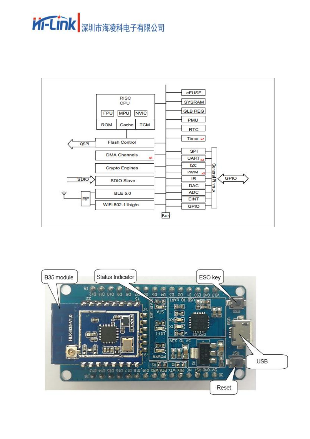
1.6. System Block Diagram
Pic 2. HLK-B35 Module architecture diagram
1.7. Test board introduction
Pic 3 Test board introduction

User Manual
第7页共30
HLK-B35
2. Function description
HLK-B35 supports serial port to WIFI STA, serial port to WIFI AP and serial port to BLE
mode.
The module is powered on by default in AP mode (IP is fixed at 192.168.169.1), as a UPD
server, port 9000, WiFi hotspot name is HLK_B35_WIFIxxxxxxxx, where xxxxxxxx is the last 4
bytes of the module's MAC address.
The Bluetooth name is HLK_B35_BLExxxxxxxx, where xxxxxxxx is the last 4 bytes of the
module's MAC address.
2.1. WIFI indicator flashing description
The module is indicated by the flashing of the LED indicator in different states, and the current
operating state of the module can be quickly known from the table:
Module status
Light flashing method
STA mode
Not connected to the router
Periodic three flashes
connected to the router
Fast flashes
Non-TCP client
Socket created successfully
Slow flashing
TCP client
Connect to the TCP server
Slow flashing
AP mode
Periodic four flashes
2.2. UART to WIFI STA
Pic 6 Module as STA
The module converts the serial port data of the device into wifi data to achieve the purpose of
device networking.
Table des matières
Autres manuels Hi-Link Module sans fil


Manuels Module sans fil populaires d'autres marques


Cooper Wiring Devices
Cooper Wiring Devices ESPIRE RF RFAPM Manuel utilisateur

Yuga
Yuga CLM920 Manuel utilisateur

Waldmann
Waldmann TALK Bluetooth Manuel utilisateur

Telit Wireless Solutions
Telit Wireless Solutions UC864-G Manuel d'installation

Ebyte
Ebyte E07-900M10S Manuel utilisateur

Quectel
Quectel SC690A Series Supplément

Panasonic
Panasonic INDUSTRY PAN9028 Guide de configuration rapide

Ebyte
Ebyte E70-433NW30S Manuel utilisateur

LongSung Technology
LongSung Technology U9507E Manuel utilisateur

Wistron NeWeb
Wistron NeWeb DNUR-S2 Manuel utilisateur

Ebyte
Ebyte E49-400M20S4 Manuel utilisateur

RF-Star
RF-Star SimpleLink RF-BM-2652P1 CC2652P Manuel utilisateur