HF HF-LPB130 Manuel utilisateur

http://www.iotworkshop.com 1 Copyright © 2013 . All rights reserved
High Flying Wi-Fi Module
Operation Guide
This document is applicable to the following series of products. This article
uses HF-LPT230 as an example to introduce the main software functions. The
differences will be specified. For the hardware description of the product and
some software functions, please refer to the user manual.
2.4GWi-Fi
HF-LPB130
HF-LPT230
HF-LPT130A
HF-LPT130B
HF-LPT330
HF-LPB135
2.4GWi-Fi
+BLE
HF-LPC300
HF-LPC330
2.4G+5G
Wi-Fi
HF-LPD100
HF-LPD130
2.4G+5G
Wi-Fi
+BLE
HF-LPF100

http://www.iotworkshop.com 2 Copyright © 2013 . All rights reserved
Table of Contents
1. Hardware Introduction...........................................................................................................3
1.1. HF-LPX30 EVK...........................................................................................................3
2. Serial Port Settings ................................................................................................................4
2.1. SecureCRTSerial Port Tool SecureCRT.................................................................4
2.2. Setting Serial Port Parameters.................................................................................4
2.3. SecureCRT Software Usage ....................................................................................4
3. Test Case.................................................................................................................................8
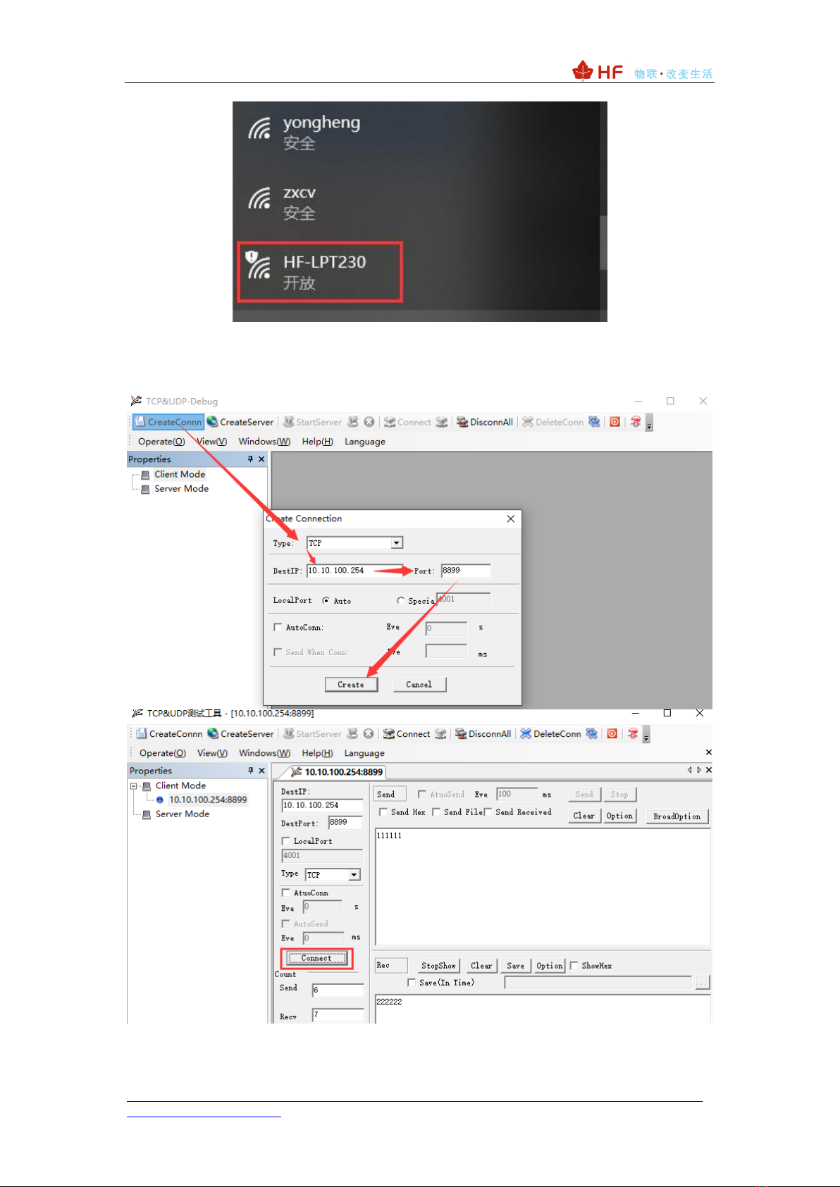
3.1. Transparent Transmission of UART and Wi-Fi Module in AP Mode...................8
3.2. Transparent Transmission of UART and Wi-Fi Module in STA Mode...............11
3.3. MQTT Transmission in STA Mode.........................................................................15
3.4. HTTP Transmissio in STA Mode............................................................................17
3.5. Heartbeat Package, Registration Package ..........................................................18
3.6. SendingAT Commands in Network Mode............................................................19
4. Firmware Upgrade................................................................................................................21
4.1. Serial Port Firmware Upgrade................................................................................21
4.2. Internal Web Page Firmware Upgrade..................................................................23
4.3. External Configuration Web Page Firmware Upgrade .......................................24
4.4. HF Udate Mass Production Tool Mode Upgrade.................................................24
4.5. AT+UPURL Command Mode Upgrade.................................................................25
5. Debug Information Function...............................................................................................27
6.1. Serial Port Log Information Output Enable...........................................................27
6. Module Hardware Description............................................................................................29
6.1. Serial Port Level Conversion..................................................................................29
6.2. Power Supply Design ..............................................................................................32
6.3. Internal antenna........................................................................................................33
7. HF-LPCX30/HF-LPF100 Module BLE THROUGHPUT .................................................34

http://www.iotworkshop.com 3 Copyright © 2013 . All rights reserved
1. HARDWARE INTRODUCTION
HF-LPX30 series is a low-power, high-performance Wi-Fi module supporting the
IEEE 802.11b/g/n wireless standard, with a maximum frequency of 160MHz,
352KB/384KB RAM, 1MB or 2MB Flash.
High Flying provides the EVK development board for the corresponding module for
functional testing and development.
1.1. HF-LPX30 EVK

http://www.iotworkshop.com 4 Copyright © 2013 . All rights reserved
2. SERIAL PORT SETTINGS
2.1. SecureCRTSerial Port Tool SecureCRT
Download address:
http://www.hi-flying.com/index.php?route=download/category&path=1_4
Unzip the folder, open to find the SecureCRT executable, and click Open.
Connect the development board to the computer with a micro USB cable and install the
USB serial port driver:
http://www.hi-flying.com/download-center-1/applications-1/driver-ft232r
Click the Quick Connect button to create a connection.
2.2. Setting Serial Port Parameters
Agreement: Serial
Port: The port to which the computer is actually connected (available via My Computer ->
Device Manager -> Ports (COM and LPT) as shown.) )
The default factory serial port parameters are as shown in the figure below. If necessary,
the AT+UART command can be used to modify the serial port parameters of the device.
2.3. SecureCRT Software Usage
Open the tool Button Bar function.

http://www.iotworkshop.com 6 Copyright © 2013 . All rights reserved
Can also edit and add commonly used AT commands with \r as the terminator.
Click the corresponding button to send "+++", the module responds with "a" and then
clicks to send "a". After the module returns "+ok", it enters the command mode.
After entering the command mode, the module can send commands, and the data input
by the main interface will be sent out immediately. The displayed data is echoed. The data in
the lower command bar will be sent only after pressing the Enter key (It needs to be displayed
after the tool is enabled.) The data sent in the command bar is marked with a carriage return,
so there is no need to add "\r" as the button bar.

http://www.iotworkshop.com 7 Copyright © 2013 . All rights reserved
The Command Window is displayed.
Notes:
1、Switching the transparent transmission mode to the command mode For
detailed procedures, refer to the user manual.
2、It is also possible to directly send the AT command in the transparent
transmission mode, and use the AT+CMDPW command to enable this function.
See the chip manual for details.
3、In the batch stage, High Flying can support the module that burns the
customized parameters, so the default parameters do not need to be configured
by the MCU.

http://www.iotworkshop.com 8 Copyright © 2013 . All rights reserved
3. TEST CASE
The software used in this article can be obtained from the High Flying website.
http://www.hi-flying.com/index.php?route=download/category&path=1_4
3.1. Transparent Transmission of UART and Wi-Fi Module in AP Mode
The test topology is as follows:
After power-on, the Power light is on, the Ready light is on, and the module is working
properly.
After the computer Wi-Fi searches for the AP hot spot of this device, it connects.

http://www.iotworkshop.com 9 Copyright © 2013 . All rights reserved
Open the TCP & UDP Debug software, create a TCP client, fill in the module's IP address
and TCP information (default AP IP: 10.10.100.254, TCP Server, 8899 port, available
AT+LANN, AT+NETP command to modify the default information), click 【Connect】establish
connection.
The two-way transmission and reception of data is completed as shown below.
Ce manuel convient aux modèles suivants
10
Table des matières
Autres manuels HF Routeur sans fil


