
H2O Rx DCH-2 Manuel utilisateur

CONDUCTIVITY-
TEMPERATURE
CONTROLLER
DCH-2
USERS GUIDE
DCH-2 Instruction manual PAGE 1

TABLE OF CONTENTS
SPECIFICATIONS......................... 3
SPECIFICATIONS (cont.).................. 4
INTRODUCTION. . . . . . . . . . . . . . . . . . . . . . . . . . 5
INSTALLATION .......................... 7
Instrument............................. 7
Electrode ............................. 7
4-20mA constant current output. . . . . . . . . . . . 8
Panelmounting......................... 9
OPERATION............................. 11
Initial check of the DCH-2. . . . . . . . . . . . . . . . . 11
TheLCDdisplay........................ 12
Selectingmodeofoperation............... 13
CALIBRATION OF THE DCH-2 . . . . . . . . . . . . . . 17
Calibratingconductivity................... 17
Pre-calibration of temperature . . . . . . . . . . . . . 17
Calibrating temperature with the electrode. . . . 18
Temperature compensation for conductivity. . . 19
Calibrating the compensation factor. . . . . . . . . 19
Settingcompensationfactor .............. 20
DCH-2 and high/low temperature alarm. . . . . . 21
OPTIONS................................ 22
WARRANTY . . . . . . . . . . . . . . . . . . . . . . . . . . . . . 23
PAGE 2 DCH-2 Instruction manual

SPECIFICATIONS
General features:
Display: 3 1/2 digit LCD display
Signal output: 4-20mA constant current output. Select
conductivity or temperature with DIP switch.
Output fully isolated from instrument.
Power: 240VAC 50Hz 7VA max.
Housing: Thermoplastic with transparent lid. Rated IP 55
Dimensions: 182(W) x 137(H) x 108(D)mm.
Conductivity
Range: 4 ranges selected with DIP switch under subpanel
0-199.0uS, 0-1999uS, 10-19,999uS,
10-199,999uS
Temperature
range: 0-100oC
Temperature
compensation: 0-100oC, fully automatic, compensation can be ad-
justed for no compensation to 20% compensation at
100oC Celsius.
Set point control: System 1 and System 2 can be configured
separately for up/down dosing with conductivity or
temperature.
Relay output: 2 relays with changeover contacts. Maximum rating
240VAC/Amps. (non inductive) Set point adjustment
fully independent over entire selected range.
Cell: 3/4" BSP thread inline type with moulded 4 pin socket
for cable connection.
(Immersion type available as
optional extra.)
Cell material: Polypropylene & stainless steel.
DCH-2 Instruction manual PAGE 3
SPECIFICATIONS (cont.)
Temperature
sensor: NTC thermistor type.
Sensor moulded into tip of electrode.
Temperature range of electrode 0-60oC.
Cable length: Three metres.
Temperature:
Range: 0oC to +199.9oC,
(resolution 0.1oC)
Accuracy: +/- 1oC
Output control: 4-20mA constant current source
(internally selected)
4mA = 0oC, 12mA = 50oC, 20mA = 100oC
Sensor: NTC Thermistor type
(rated temperature range 0-250oC)
Size: 6mm Dia. x 120mm length.
Sensor body: 316 stainless steel with moulded 3 metres cable.
FIG.1
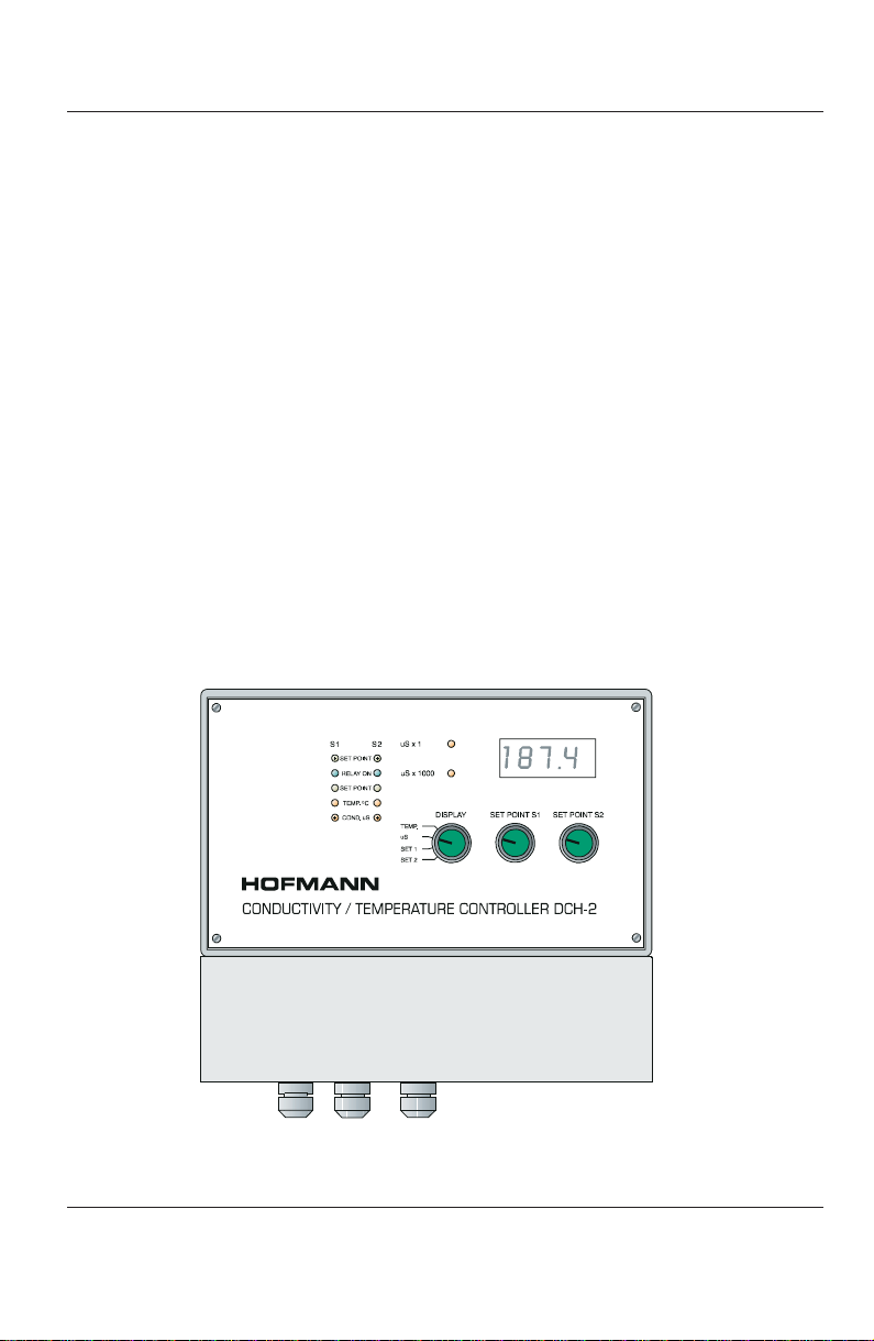
THE LCM-2 CONTROLLER
PAGE 4 DCH-2 Instruction manual

INTRODUCTION
The DCH-2 is well suited to operate in the hot and damp conditions
oftenpresentaroundboilers,coolingtowersandindustrialsitesingeneral.
Moisture and accidental sprays are sealed off from the sensitive parts of
the instrument with the transparent lid securely held in place with the 4
fasteners supplied with the unit. All cables feed through cable glands
situated on the underside of the DCH-2.
The LCD 3 1/2 digit display shows either temperature, conductivity or
SET POINT 1 and 2 when selected with the DISPLAY switch. Two small
red LED’s indicate the x1 or x1000 conductivity range selected. The
SYSTEM 1 and SYSTEM 2 controls with corresponding green LED’s
adjust the desired set point.
(See Fig.2)
The SET POINTS can be configured for up/down dosing, tracking the
conductivity or temperature. DIP switch 2 located under the subpanel set
the desired configuration.
3 1/2 LCD DIGITAL
DISPLAY
ADJUSTABLE SET
POINT 1 AND 2
WITH GREEN LED
LIGHTS ABOVE.
REMOVE SUBPANEL
FOR SCREW TERMI-
NALS, MODE
SELECTOR AND
CONDUCTIVITY FINE
ADJUSTMENT.
LED ARRAY TO INDICATE
UP/DOWN, SETPOINT
AND COND/TEMP MODE.
DISPLAY SELECTOR FOR
SET POINT
CONDUCTIVITY
TEMPERATURE.
FIG.2
FRONT PANEL LAYOUT
DCH-2 Instruction manual PAGE 5

A1AMPfusesituatedinsidetheenclosureonlyprotectstheinstrument.
The relays have change over contacts and require their separate fusing
to comply with safety rules.
Removing the sub panel reveals the screw terminals for all electrical
connections, configuration switches, calibrations for conductivity and the
temp.compensation.Thelegendfortheterminalsprintedonthesubpanel
allows an easy identification of the appropriate connections.
The DCH-2 can monitor and/or control conductivity and temperature
simultaneously in an installation with the proper selection of the SET
POINT configuration. The inherent accuracy of the 4-20mA constant
current output and electrical isolation makes it possible to interface into a
micro processor or logic controller to further expand the combination of
installations with the DCH-2.
(See 4-20 mA constant current output.)
FIG.3
TERMINAL CONNECTORS AND ADJUSTMENTS
PAGE 6 DCH-2 Instruction manual

INSTALLATION
Instrument
Installation and setting up of the DCH-2 is easy and straight forward.
No special tools are required.
(See Fig.2)
The 4 screws are inserted
through 4 corner holes
(locking holes for the transparent lid)
and also
fastened through them with a screw driver. All cables are fed through the
3 cable glandsand terminated at the appropriate terminals. Alwayscheck
that the stripped wire end is inserted above the small sliding metal block
inside the terminal to ensure proper connection when tightening the
terminal screw.
(See Fig.3)
If the control relays are used to switch 240VAC a wire link may be
connected between the 240V active terminal and the common contact of
the relays.
Electrode
The cell is mounted in line into a 3/4" BSP Tee. The T-piece used to
install the electrode must be PVC to ensure that no short circuit between
the stainless steel electrodes and pipe fitting occurs. A conduction leak-
age may also affect the accuracy of the instrument reading if a metal
T-piece is used.
The 4 core cable plugs into the 4 pin socket situated on the back of the
electrode. Never cut the cable or rejoin the 4 wires to shorten or lengthen
the cable, as this will result in unreliable and inferior performance. Always
reconnect the whole length of the cable to the 4 pin plug. Longer cables
up to 10 metres can be supplied on request.
The electrode in the standard package contains a 4 pin socket and a
3 metre cable. This greatly simplifies an installation where the cable is
wired through a conduit or is fastened to a walland the electrode screws
into a pipe. For situations where it is necessary to simply immerse the
electrode into the solution a special model with a 3 metre cable directly
moulded to the body can be supplied on request.
DCH-2 Instruction manual PAGE 7

The polypropylene electrode is used in applications with fluid tempera-
turesupto60
oC. A teflon electrode and the stainless steel temperature
sensorare usedforapplicationswithfluidtemperatureshigherthan60oC.
F
The T-piece used to install the electrodeinline must be PVC to ensure
that the LCM-2 performs accurate and reliable.
4-20mA constant current output
Switch No. 5 of DIP switch 2 selects the conductivity or temper-ature
signal to drive the 4-20mA current output. The DISPLAY switch setting
has no effect on the selected mode of 4-20mA current output.
Conductivity range 0-200uS Conductivity range 0-2000
0uS = 4mA 0uS = 4mA
100uS = 12mA 1000uS = 12mA
200uS = 20mA 2000uS = 20mA
Conductivity range 0-20,000uS Conductivity range 0-200,000uS
0uS = 4mA 0uS = 4mA
10,000uS = 12mA 100,000uS = 12mA
20,000uS = 20mA 200,000uS = 20mA
Temperature range
0oC=4mA, 50
oC=12mA, 100
oC=20mA
F
The DCH-2 now features a fully isolated 4-20mA output and can be
directly connected to other devices or micro processors withoutaffect-
ing the performance of the DCH-2.
The 4-20mA output is DC current. The signal wires therefore must be
connectedwiththerightpolarityobserved.Anyequipmentconnectedwith
reversed wires will not function at all!
PAGE 8 DCH-2 Instruction manual

F
Normal coaxial cable such as TV cable may be used if desired with
the shield providing the negative connection.
Panel mounting.
Insert a round headed screw into the panel where the instrument is to
be attached. This screw determines the centre of the instrument location.
(See Fig.4)
Slide the instrument over the slot opening at the back, check
that the unit hangs level and secure it with two screws inserted through
the slots at the two bottom corners.
FIG.4
ESCUTCHEON FOR THE DCH-2
DCH-2 Instruction manual PAGE 9

PAGE 10 DCH-2 Instruction manual
Table des matières
Manuels Régulateurs de température populaires d'autres marques

Swegon
Swegon LUNAd MB Manuel utilisateur

Lucky Reptile
Lucky Reptile Thermo Control II Manuel utilisateur

SENSORMETRIX
SENSORMETRIX Argon 100 Manuel utilisateur

Fuji Electric
Fuji Electric PXE4 Manuel utilisateur

Yuyao gongyi
Yuyao gongyi XMT-808 series Manuel utilisateur

Selec
Selec TC544C Manuel utilisateur


