H2flow levelsmart Manuel de l'opérateur

Instruction Manual
English
levelsmart™
Wireless Autofill
USER INSTRUCTION MANUAL

1. Supporting Documents & Media ........................................................................................3
2. Description ......................................................................................................................3
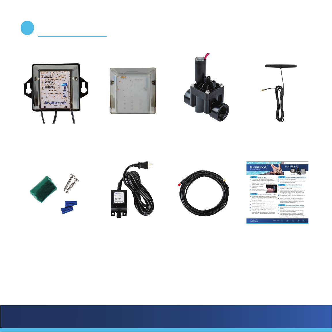
3. What’s in the Box...............................................................................................................5
4. Installation and Setup........................................................................................................6
Install the Valve .....................................................................................................................................6
Install and connect the Valve Controller...............................................................................................7
Connect the Antenna ............................................................................................................................7
Install the Power Supply and connect to the Valve Controller ............................................................8
Pair the Level Sensor and Valve Controller..........................................................................................8
Mount the Level Sensor ........................................................................................................................9
Mount the Antenna................................................................................................................................10
Set and calibrate the water level..........................................................................................................10
5. Testing the Valve after Pairing ...........................................................................................11
6. Adjusting the Water Level..................................................................................................12
7. Valve Flow Control Adjustment..........................................................................................13
8. Troubleshooting ................................................................................................................14
9. Notes ......................................................................................................................15
10. Warranty .........................................................................................................Back Cover
CONTENTS

levelsmart™
Wireless Autofill
3
While the products’ installation and setup are covered in the Quick Start Guide, this manual will provide a more
detailed description of the product, its installation, setup, and troubleshooting. A complete list of the support
media is as follows:
a. Quick Start Guide: Included in the product packaging box, this document will cover both the installation
& setup and will satisfy the needs of most installers.
b. Product Manual (this document): Provides an expanded description of the product, its installation,
setup, and troubleshooting.
c. Media: The following QR Code will take you to avaliable videos that cover the
installation and commissioning of the system.
SUPPORTING DOCUMENTS & MEDIA
1
LevelSmart is a sophisticated, yet simple to install, wireless control system designed to maintain the desired water
level in Pools, Spas, Water Features, Ponds, or Tanks.
Unlike other level control systems, LevelSmart does not require underground wiring or plumbing from the
equipment pad to the body of water.
Innovative and patented sensing methods ensure that LevelSmart provides a reliable and user-friendly auto-
lling solution.
The schematic (Fig.1.0) on page 4 of this manual shows a typical LevelSmart installation.
DESCRIPTION
2

levelsmart™
Wireless Autofill 4
levelsmart
SENSOR
levelsmart
VALVE CONTROLLER
Fig.1.0
The overall principle of operation of the LevelSmart system is as follows:
During setup, the Level Sensor is taught the desired water level. When the Level Sensor detects a low level, it
communicates this condition to the valve controller via a wireless signal. The valve controller opens the water
supply valve for 7 minutes to restore the desired level. Every 30 minutes, the valve controller will repeat the
process until the desired water level has been achieved. A maximum number of (8) repeat simultaneous cycles
will occur, aer which an Alarm LED will illuminate on the valve controller. Most low water level conditions will
be restored within 1 to 2 cycles.
levelsmart™
Wireless Autofill
5
LevelSmart valve
controller
LevelSmart level sensor Automatic valve Antenna
Accessory kit: epoxy,
(x2) wire nuts, (x2)
screws
Power supply Antenna extension
cable (optional)
Quick Start Guide
WHAT’S IN THE BOX
3

levelsmart™
Wireless Autofill 6
While most aspects of the installation can be undertaken by a person with good DIY skills, the installation of the
Valve should only be undertaken by a person that is skilled or procient in the plumbing of PVC pipe.
The following step-by-step procedures are required for the systems installation:
a. Install the Valve
b. Install and connect the Valve Controller
c. Connect the Antenna
d. Install the Power Supply and connect to the Valve Controller
e. Pair the Level Sensor and Valve Controller
f. Mount the Level Sensor
g. Mount the Antenna
h. Set and calibrate the water level
INSTALLATION AND SETUP
4
a) Installing the Valve
The valve has 1” Female NPT sockets on each end. The valve also has a directional arrow molded into the top of
the sockets, it is essential that the valve is installed so that the arrow points in the direction of water ow from its
source to the pool return line. The most common method of installing the valve is via a ‘T’ that you will plumb
into the existing return line to the pool. The preferred location is aer the lter and before any chemical injection
points. An appropriately sized adapter with a 1” female thread should be glued into the socket of the ‘T’. A short
1” NPT nipple should be threaded into the adapter and the downstream side of the valve threaded onto the other
end of the nipple.

levelsmart™
Wireless Autofill
7
If you are able to hard plumb the upstream side of the valve into a freshwater supply line, then this is the
preferred method. However, you should make sure that a provision is made to drain this line for winterizing your
equipment. If hard plumbing is not an option, then you can connect the upstream side of the valve to a garden
hose and spigot. Thread into the upstream side of the valve a 1” male NPT to ¾” female NPT adapter. Into this,
thread in a ¾” male NPT to ¾” MHT (male hose thread) adapter. Now connect a suitable length garden hose
from the valve to a spigot. If the spigot serves another garden hose, install a ‘Y’ and connect both the LevelSmart
hose and the existing garden hose. Make sure that the homeowner is informed that the valve on the ‘Y’ to the
LevelSmart is never turned o. If possible, ax a tag to inform people not to turn it o.
Important Note: Many local jurisdictions require a non-return / backow preventer when installing ll lines
or irrigation systems to city water supplies. It is the installer’s responsibility to check into this and to install an
appropriate device if necessary.
b) Install and connect the Valve Controller
The valve controller should be mounted on the wall next to the equipment pad and no more than 6 feet from the
valve installed in section a) above. Stainless steel screws and plastic wall plugs are provided for your convenience.
The 6-foot-long black wire (with red and black wire tails), coming from the bottom right-hand side of the valve
controller should be connected to the two red wires connected to the solenoid of the valve. Note that this is 24
VAC power and therefore not polarity sensitive; the black and red wires coming from the valve controller can be
connected to either of the red wires coming from the valve. Wire nuts are provided.
c) Connect the Antenna
Connect the Antenna plug to the socket on the lower le of the valve controller. Do not mount the Antenna at
this time, but place it loosely in a location where it can see the pool and where it can be adhered if a successful
pairing of the Level Sensor to the Valve Controller is achieved. Keep the Antenna at least 12 inches away from any
metal as this will interfere with the wireless communication between the Level Sensor and Valve Controller.

levelsmart™
Wireless Autofill 8
d) Install and connect the Power Supply to the Valve Controller
Identify a 120 VAC power outlet at the equipment pad and mount
the power supply to the wall or zip tie it to a suitable structure that
will be close enough to connect the Valve Controllers power cable
to the 2-pin outlet at the base of the Power Supply.
Connect the Power Supply’s outlet 2-pin socket to the Valve
Controller’s 2-pin plug and tighten the nut to seal the connection
from water ingress.
Connect the Power Supply’s 120 VAC plug into the outlet.
At this point you should see the three LED’s on the front of the
Valve Controller ash in a repetitive sequence from the bottom to
the top (green, yellow red).
e) Pair the Level Sensor and Valve Controller
Take the Level Sensor (Fig.1.2) to the area of the pool that
you intend to install it. The throat of a skimmer is a common
location. Do not mount the Level Sensor yet. With the Level
Sensor close to the installation location, remove the magnet
from the front face. You will now see three ashes of the green
LED at the top center of the Level Sensor, this indicates that the
Level Sensor has initiated its pairing sequence with the Valve
Controller.

levelsmart™
Wireless Autofill
9
Leaving the Level Sensor at the pool side, go back to the Valve
Controller (Fig.1.3)
When looking at the Valve Controller, you should see the yellow
(Action) LED ash once per second, 30 times. Aer this, the yellow
LED will ash every 4 seconds for a further 2 minutes. Finally, the
green (Level Sensor) LED light will illuminate. This solid green Level
Sensor LED indicates a successful pairing and that the intended
location for the Level Sensor in the pool is a good one.
If a solid green Level Sensor LED does not appear at the end of the
2.5 min, then the Valve Controller will either go back into a pairing
mode (the three LED’s scrolling from bottom to top), or a solid yellow
Action LED will illuminate.
If the unit goes back into either of these conditions, we need to move the Level Sensor or Antenna to dierent
loations so that they can better see each other. Alternatively, the Antenna’s cable may need to be extended using
the optional 25-foot cable.
If the system does not go back into pairing mode, simply unplug the power supply for 10 seconds before plugging
it back in again.
f) Mount the Level Sensor
Once a successful pairing has occurred, we can go ahead and install the Level Sensor. Before doing so, bring the
water to the desired level.
It is critical to thoroughly clean / scrub the area where the Level Sensor is to be installed. Now thoroughly dry the
area above the water line where the Level Sensor is to be mounted.

levelsmart™
Wireless Autofill 10
Remove the outer plastic skin from the two-part epoxy putty. Knead the epoxy thoroughly until its color is
consistent (no white streaks). To protect the face of the Sensor from the epoxy, place the plastic Ziplock bag in
the palm of your hand and then place the Level Sensor, face down, on top of the bag. Now evenly spread all of
the mixed putty onto the back of the Level Sensor while trying to avoid any coming too close to the edges. Gently
place the Level Sensor on the wall of the pool, making sure to a) keep the upper part of the back of the Level
Sensor and the side of the pool dry, and b) ensuring the desired water level is somewhere between 0.5 to 1.5
inches up from the bottom of the Level Sensor’s face. Press the Level Sensor on as hard as you can and give it a
small rotational movement back and forth to achieve a more even spread of the putty. Make sure that the Level
Sensor is vertical and then keep pressure on the face for at least 90 seconds. Do not try to pull it o aer the 90
seconds as the putty will continue to cure for the next hour or two.
g) Mount the Antenna
Peel the backing tape o the rear of the Antenna. Mount the Antenna close to where it was located during pairing
process. Make sure to not mount the Antenna on or within 12 inches of metal.
h) Set and calibrate the water level
This step will teach the LevelSmart system the desired water level that it is to
maintain.
With the water at its desired level, place the magnet over the bottom right
corner of the Level Sensor for 2 seconds before removing it (see Fig.1.4).
A green LED will appear at the top center of the Level Sensor and will ash
three times; this indicates that calibration has begun. A green Sensor will also
ash on the Valve Controller for about one-minute as the water level is set.
The calibration process will conclude with a solid green Sensor light on the
Valve Controller. The LevelSmart may start a ll cycle for 7 minutes aer this
stage – this is normal. An indication that the valve is open and water is being
added is indicated by the Action LED being illuminated.
Fig.1.4
Autres manuels pour levelsmart
1
Table des matières


