GSI Group PNEG-1499 Manuel utilisateur
1
PNEG-1499 High / Low Thermostat
Digital High / Low Thermostat
INSTALLATION AND OPERATION
PNEG-1499
PNEG-1499
Date: 2-1-06

2
PNEG-1499 High / Low Thermostat
_____
1. All wire connections
_____
2.
Factory values programmed
_____
a. Value 1 set to ( F )
_____
b. Value 2 or “S1” set to ( 130 )
_____
c. Value 3 or “DIF1” set to ( 5 )
_____
d. Value 4 set to ( H1 )
_____
e. Value 5 or “S2” set to ( 100 )
_____
f. Value 6 or “DIF2” set to ( 5 )
_____
g. Value 7 set to ( H2 )
_____
3.
All items included in packaging.
_____ 4. Safety Decal Installed on side of Thermostat
_____
5.
Aesthetic appearance
_____
6.
Manual
_____
7.
Vendor Instruction Sheet
Tester Signature___________________________________
Date_________________________
CHECK LIST

3
PNEG-1499 High / Low Thermostat
TABLE OF CONTENTS
Safety
.......................................................................................................
4
Safety Guidelines
...........................................................................
4
Safety Decals
.................................................................................
7
Roof Damage Warning and Disclaimer
..........................................
8
Installation
.................................................................................................
9
Thermostat Connection to Standard Heater Control
...............................
10
Thermostat Connection to Deluxe Heater Control
...................................
11
Programming Setpoint Values
.................................................................
12
Parts
.....................................................................................................
13
Appendix
.................................................................................................
14
Warranty
..................................................................................................
15
4
PNEG-1499 High / Low Thermostat
This manual contains information that is important for you, the owner/operator, to know and under-
stand. This information relates to protecting
personal safety
and
preventing
equipment problems
. It is the responsibility of the owner/operator to inform anyone
operating or working in the area of this equipment of these safety guidelines. To help you
recognize this information, we use the symbols that are defined below.
Please read the manual and pay attention to these sections. Failure to read this manual
and it’s safety instructions is a misuse of the equipment and may lead to serious injury or death.
SAFETY GUIDELINES
DANGER
indicates an imminently hazardous situation which,
if not avoided, will result in death or serious injury.
This is the safety alert symbol. It is used to alert you
to potential personal injury hazards. Obey all
safety messages that follow this symbol to avoid pos-
sible injury or death.
WARNING
indicates a potentially hazardous situation which, if
not avoided, could result in death or serious injury.
CAUTION
indicates a potentially hazardous situation which, if
not avoided, may result in minor or moderate injury.
CAUTION
used without the safety alert symbol indicates a
potentially hazardous situation which, if not avoided, may result in
property damage.
NOTE
indicates information about the equipment that you
should
pay special attention to.
SAFETY
5
PNEG-1499 High / Low Thermostat
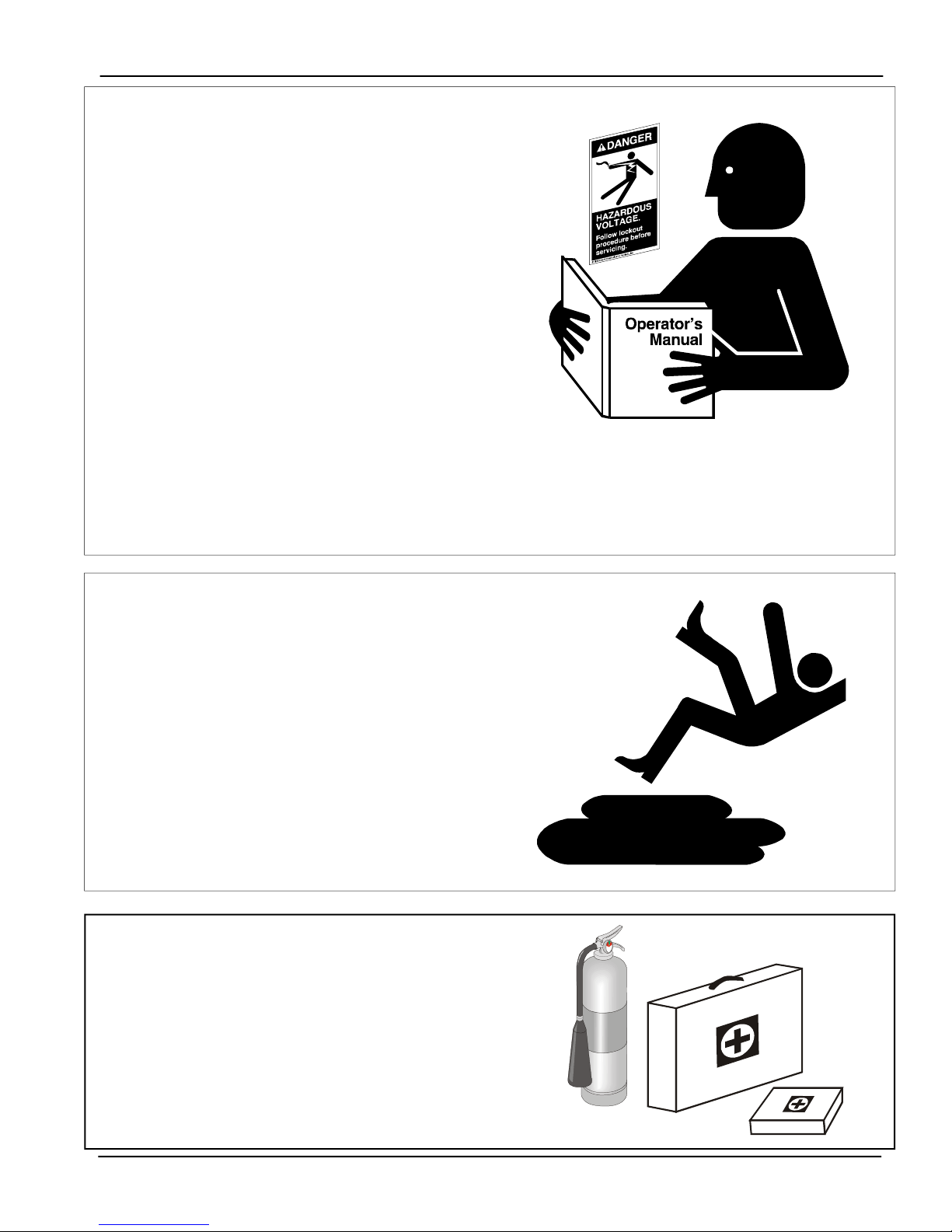
PREP
ARE FOR EMERGENCIES
Be prepared if fire starts.
Keep a first aid kit and fire extinguisher handy.
Keep emergency numbers for doctors, ambulance
service, hospital, and fire department near your
telephone.
PRACTICE SAFE MAINTENANCE
Understand service procedures before doing
work. Keep area clean and dry.
Never lubricate, service, or adjust machine while
it is in operation. Keep hands, feet, and clothing
from rotating belt and idlers.
Keep all parts in good condition and properly
installed. Fix damage immediately. Replace
worn or broken parts. Remove any build up
grease, oil, or debris.
FOLLOW SAFETY INSTRUCTIONS
Carefully read all safety messages in this
manual and safety signs on your equipment.
Keep signs in good condition. Replace missing
or damaged safety signs. Be sure new equip-
ment components and repair parts include the
current safety signs. Replacement safety signs
are available from the manufacturer.
Learn how to operate the machine and how to
use controls properly. Do not let anyone operate
without instruction.
Keep your machinery in proper working condi-
tion. Unauthorized modifications to the machine
may impair the function and/or safety and affect
machine life.
If you do not understand any part of this manual
and need assistance, contact your dealer.
SAFETY
6
PNEG-1499 High / Low Thermostat
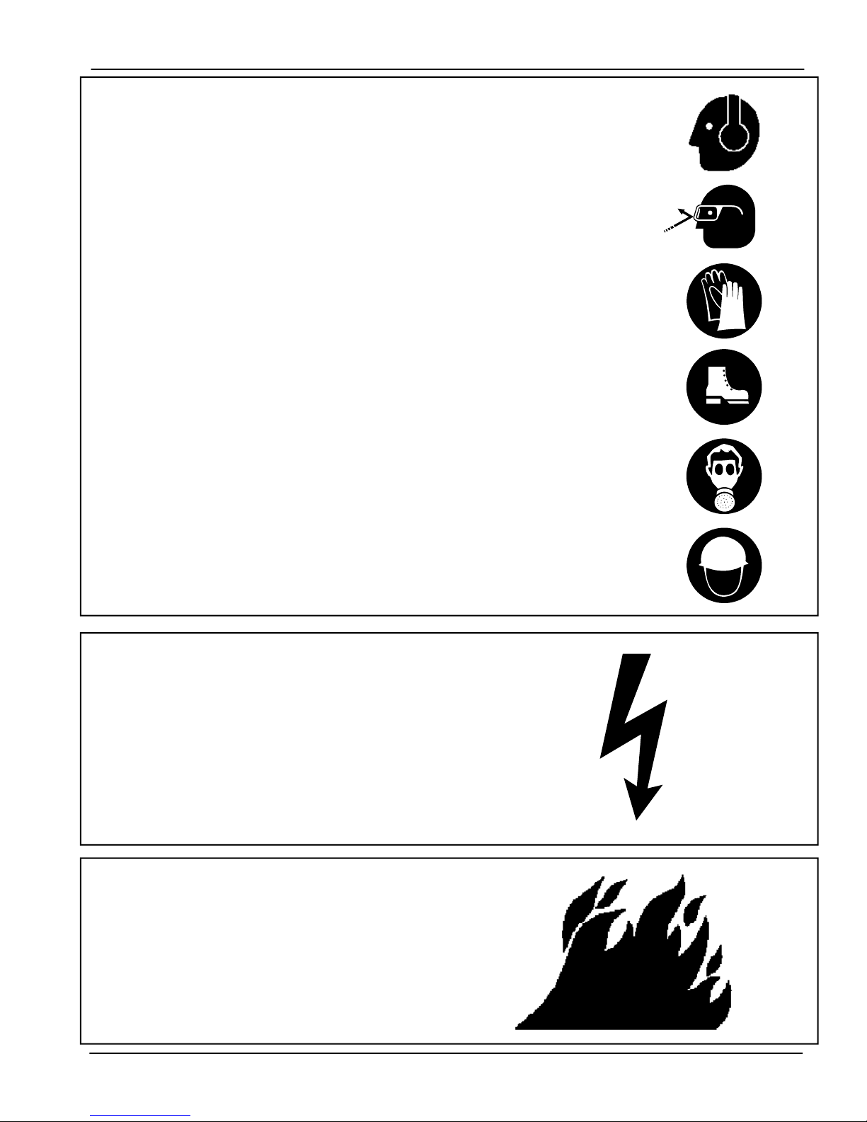
WEAR PROTECTIVE CLOTHING
Wear close fitting clothing and safety equipment
appropriate to the job.
Ear Plugs or Muffs should be worn at all times to
protect ears from high noise levels.
Safety glasses should be worn at all times to protect
eyes from debris.
Wear gloves to protect your hands from sharp edges
on plastic or steel parts.
A respirator may be needed to prevent breathing
potentially toxic fumes and dust.
Wear hard hat and steel toe boots to help protect
your head and toes from falling debris.
Eye Protection
Gloves
Steel Toe
Boots
Respirator
Hard Hat
INST
ALL
& OPERA
TE ELECTRICAL
EQUIPMENT PROPERL
Y
Electrical controls should be installed by a qualified
electrician and must meet the standards set by the
national electrical code and all local and state
codes.
Disconnect and lock out all power sources before
installing wires/cables or servicing equipment .
Hearing Protection
INST
ALL
& OPERA
TE GAS-FIRED
EQUIPMENT PROPERL
Y
Fuel supply should be installed by a qualified gas
technician and must meet local and state codes for
gaseous fuel supplies.
Disconnect and lock out all fuel sources before
servicing equipment .
SAFETY
7
PNEG-1499 High / Low Thermostat
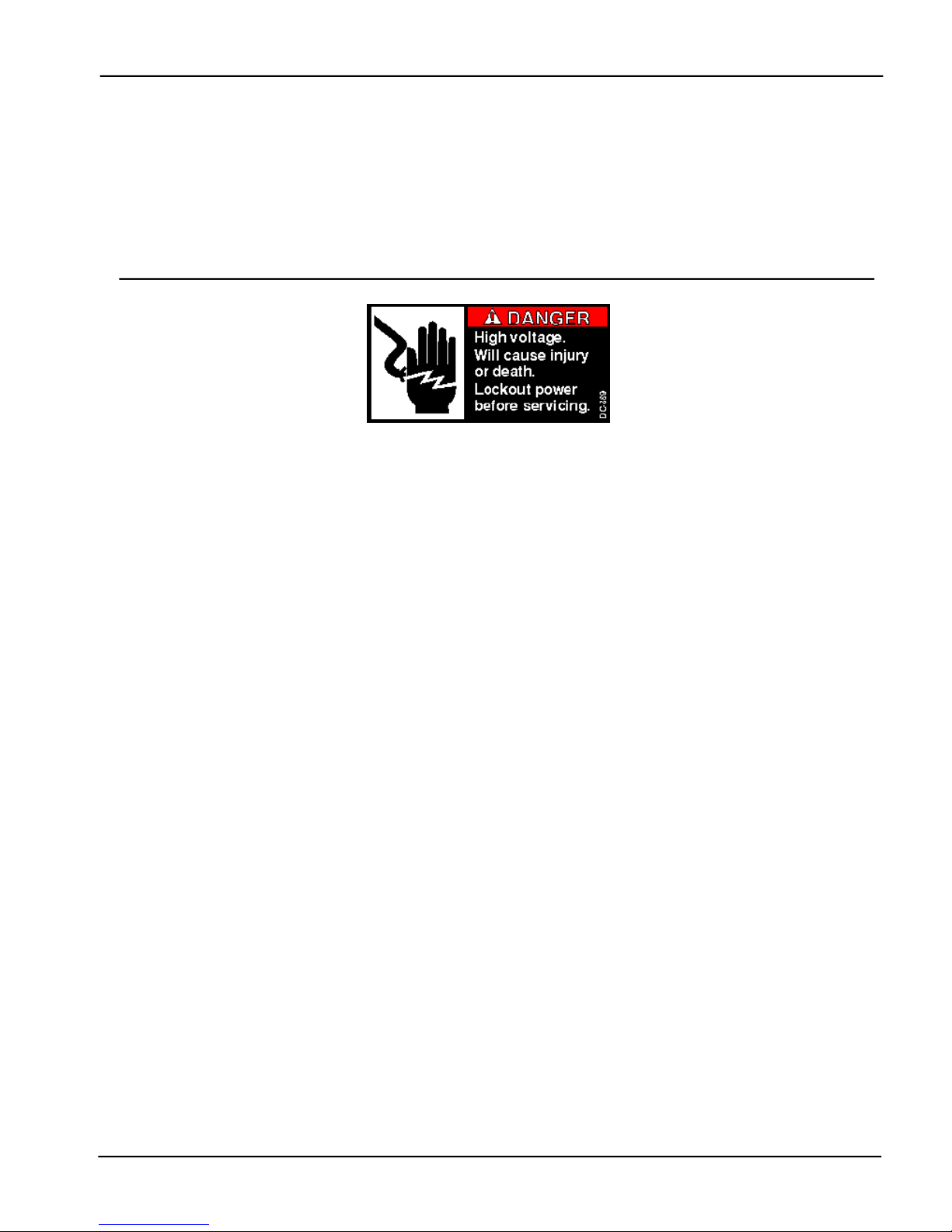
SAFETY DECALS
Safety decals should be read and understood by all people in the grain
handling area. If a decal is damaged or is missing contact:
The GSI Group, Inc.
1004 E. Illinois St.
Assumption, IL 62510
217-226-4421
A free replacement will be sent to you.
Part Number: DC-889
Size: 2.813” x 1.375”
Located on front of thermostat.
8
PNEG-1499 High / Low Thermostat
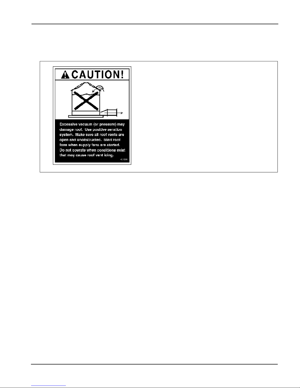
Roof Damage Warning And Disclaimer
GSI DOES NOT WARRANT ANY ROOF DAMAGE CAUSED
BY EXCESSIVE VACUUM OR INTERNAL PRESSURE FROM
FANS OR OTHER AIR MOVING SYSTEMS. ADEQUATE
VENTILATION AND/OR "MAKEUP AIR" DEVICES SHOULD
BE PROVIDED FOR ALL POWERED AIR HANDLING SYS-
TEMS. GSI DOES NOT RECOMMEND THE USE OF DOWN-
WARD FLOW SYSTEMS (SUCTION). SEVERE ROOF DAM-
AGE CAN RESULT FROM ANY BLOCKAGE OF AIR PAS-
SAGES. RUNNING FANS DURING HIGH HUMIDITY/COLD
WEATHER CONDITIONS CAN CAUSE AIR EXHAUST OR
INTAKE PORTS TO FREEZE.
SAFETY
General Safety Statements
Thank you for choosing a GSI Group product.
It is designed to give excellent performance and ser-
vice for many years.
It is the plan of The GSI Group to improve its
product whenever possible and practical to do so. We
reserve the right to change, improve, and modify prod-
ucts at any time without obligation to make changes,
improvements, and modifications on equipment sold pre-
viously.
The principal concern of the The GSI Group Inc.
("GSI") is your safety and the safety of others associ-
ated with grain handling equipment. This manual is writ-
ten to help you understand safe operating procedures,
and some of the problems that may be encountered by
the operator or other personnel.
As owner and/or operator, it is your responsibility to
know what requirements, hazards and precautions ex-
ist, and to inform all personnel associated with the equip-
ment, or who are in the dryer area. Avoid any alter-
ations to the equipment. Such alterations may produce
a very dangerous situation, where serious injury or death
may occur.
THIS MANUAL
DESCRIBES THE INST
ALLA
TION
AND OPERA
TION OF
A
DIGIT
AL
HIGH/LOW THER-
MOSTAT. THIS PRODUCT IS AN IDEAL
ACCESSORIY TO THE HEATERS USED FOR THE
CONDITIONING OF CORN, SOYBEANS, AND OTHER
SELECT GRAINS. ANY OTHER USE IS CONSID-
ERED A MISUSE OF THE PRODUCT.
9
PNEG-1499 High / Low Thermostat
INSTALLATION
1.
Mount the thermostat control on the right side of
the fan transition. Locate a suitable location on the
bin wall that will allow the power cord to reach the
heater and the control to be at eye level for easy ac-
cess.
2.
Use the S-280 self-drilling screws provided in the
packaging to mount the control.
3.
Run the power cord to the heater control box and
make the connections as shown in the electrical con-
nection section of this manual.
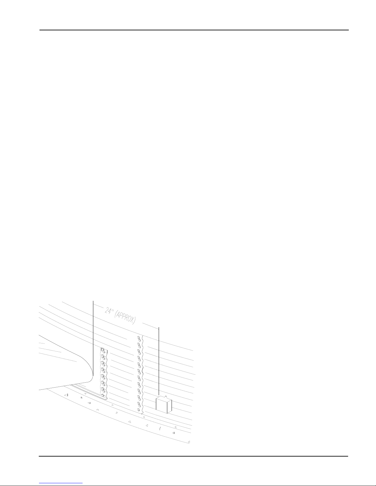
4.
Mount the thermostat sensor 24” to the RIGHT of
the transition. Use the C-8058 Sensor Mounting Plate
as a template.
This part has holes to match the hills of
a 2.66” and 4.00” bin sidewall.
5.
Use the S-280 screws provided to mount the C-8058
plate on the sidewall. The large hole on the plate should
be centered on a valley of the bin corrugations. The
plate should be mounted approximately in the center of
the plenum at the closest valley.
6.
Use the hole in the mounting plate as a guide and
drill a pilot hole. Once the pilot hole is drilled in the
sidewall, remove the mounting plate.
7.
With the plate removed, enlarge the pilot hole to 1/
2” diameter.
8.
Attach the Sensor of the thermostat to the mounting
plate using the C-8057 Cord Connector. The Sensor
should extend approximately 3.00” beyond the plate. If
not, then adjust the sensor length by loosening the cord
connector and moving the Sensor.
9.
Insert the Sensor into the 1/2” hole and reattach the
mounting plate using the S-280 screws.
10.
Caulk the area around the mounting plate to seal
any openings.
Mount the Sensor approximately 24” to the
RIGHT of the transition.
Installation Instructions
10
PNEG-1499 High / Low Thermostat
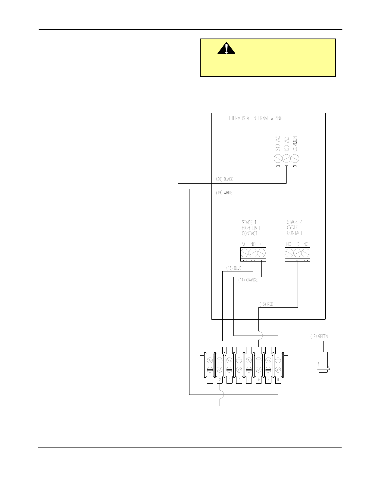
ELECTRICAL CONNECTION
Standard electrical safety practices and codes
should be used when working with a heater. Refer
to the National Electric Code Standard Handbook
by the National Fire ProtectionAssociation. A quali-
fied electrician should make all wiring installations.
DANGER
ALWAYS DISCONNECT AND LOCK OUT POWER
BEFORE WORKING ON OR AROUND HEATER.
Thermostat Connection to
Standard Terminal Strip
1.
Connect power cord to fan control box.
2.
Connect the BLACK 120VAC power wire
to terminal 2.
3.
Connect the WHITE Neutral wire to
terminal 8.
4.
Connect the BLUE Stage 1 N/O wire to
terminal 5.
5.
Connect the ORANGE Stage 1 Common
wire to terminal 8.
6.
Connect the RED Stage 2 Common wire
to terminal 6.
7.
Connect the GREEN Stage 2 N/O wire
to the high/low light.
Table des matières
Autres manuels GSI Group Thermostat

Manuels Thermostat populaires d'autres marques

EWELLY
EWELLY EW-181 Manuel utilisateur

Prolon
Prolon T1100 Instructions d'installation

Computherm
Computherm Q20 Manuel utilisateur

Heatmiser
Heatmiser neoStat Manuel utilisateur

Aube Technologies
Aube Technologies TH111GFCI-NP 240 VCA Manuel utilisateur

Mars
Mars HEAT CONTROLLER IR Wireless Thermostat Manuel utilisateur


