Grundig GCA-B1323V Manuel utilisateur
GCA-B1323V.5.3.28.11.2011
Owner's Manual
EN
© ASP AG
Cameras & Domes
GCA-B1323V 1/3" CCD Col/B&W Fixed Dome Camera
GCA-B0322V 1/3" CCD Col/B&W Fixed Dome Camera
GCA-B0323V 1/3" CCD Col/B&W Fixed Dome Camera w/ IR LED
GCA-B0325V 1/3" CCD Col/B&W Fixed Dome Camera, WDR
GCA-B0326V 1/3" CCD Col/B&W Fixed Dome Camera IR LED & WDR


Content:
1. Available Versions 1
2. Important Safety Instructions 2
3. Package Contents 2
4. Installation 3
1. Part Names 3
2. Base Installation 4
3. Angle Mount Bracket Advantage 5
4. Mounting Housings to Electrical Junction Boxes 5
5. Connections 6
6. 3-Axis Gimbal Adjustment 6
7. Zoom & Focus Adjustment 7
5. OSD Menu 7
1. OSD Controls 7
2. Main menu 8
3. Camera Setup 9
4. Intelligence 16
5. Privacy Zone 18
6. Other Set 19
7. Communication 19
8. System Info 19
9. Language 20
1
English

1. Available Versions
These instructions apply to the following
products. For the different properties of the
products please refer to the table.
2. Important Safety Instructions
Be sure to use only the standard adapter that is specified in the specification sheet.
Using any other adapter could cause fire, electrical shock, or damage to the product.
Incorrectly connecting the power supply or replacing battery may cause explosion, fire,
electric shock, or damage to the product. Do not connect multiple products to one single
adapter. Exceeding the capacity may cause abnormal heat generation or fire.
Do not place conductive objects (e.g. screwdrivers, coins or any metal items) or
containers filled with water on top of the product. Doing so may cause personal injury
due to fire, electric shock, or falling objects.
If any unusual smells or smoke comes from the unit, stop using the product. In such
case, immediately disconnect the power source and contact the service center.
Continued use in such a condition may cause fire or electric shock.
If this product fails to operate normally, contact the nearest service center. Never
disassemble or modify this product in any way. (GRUNDIG is not liable for problems
caused by unauthorised modifications or attempted repair.)
To prevent fire or electric shock, do not expose the inside of this device to rain or
moisture.
3. Package Contents
These parts are included:
2English
4. Installation
Do not install the product in a location subject to high temperature (over 50°C), low
temperature (below -10°C), or high humidity. Doing so may cause fire or electric shock.
Keep out of direct sunlight and heat radiation sources. This may cause fire. Avoid aiming
the camera directly towards extremely bright objects such as the sun, as this may
damage the image sensor.
Do not install the unit in humid, dusty or sooty locations. Doing so may cause fire or
electric shock. Install it in a place with good ventilation.
When installing the unit, fasten it securely and firmly. A falling unit may cause personal
injury.
If you want to relocate the already installed product, be sure to turn off the power and
then move or reinstall it.
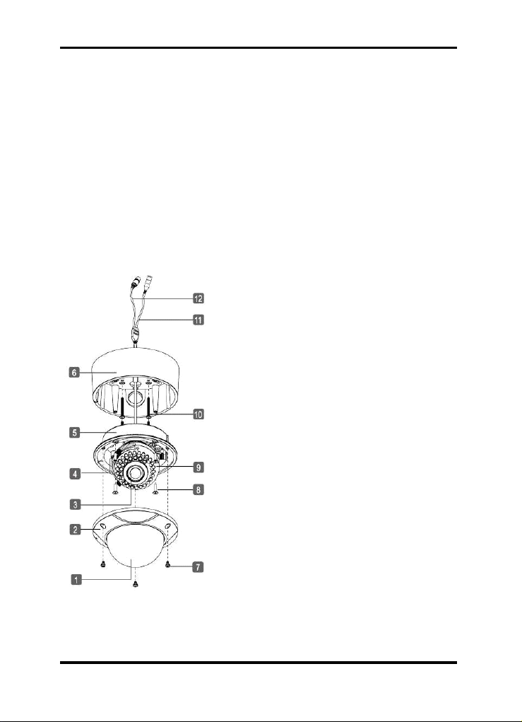
4.1. Part Names
1. Bubble
2. Dome Cover Ring
3. Lens
4. Service Monitor Output Port
5. Flush Mount Base
6. Surface Mount Plate
7. Assembly Screws (Torx M4x8)
8. Assembly Screws (Philips M4x14)
9. Camera Control Board
10. Mounting Screws (St4x38)
11. Power Input Terminal: AC 24V/DC 12V
12. Video Output Connector - NC
3
English
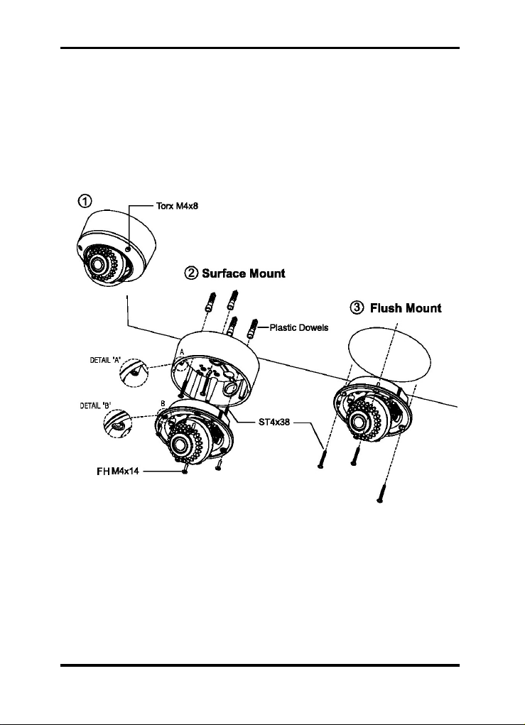
4.2. Base Installation
1. Remove the dome cover by loosening the 3 screws. Use the Torx wrench supplied.
2. Surface Mount :
Using the four ST4x38 screws, mount the surface plate to a sturdy surface.
Using the four M4x14 screws, affix the flush mount base to a surface plate.
(For flush mount application, disregard section 2.)
3. Flush Mount :
Using the four ST4x38screws, affix the flush mount base to a sturdy surface.
4English
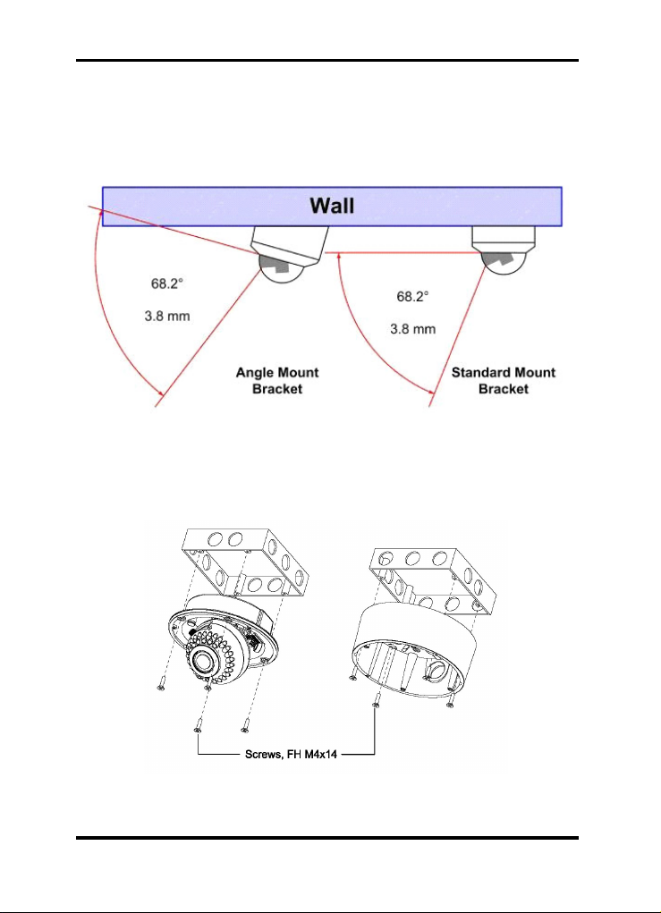
4.3. Angle Mount Bracket Advantage
With a standard bracket, a vandalproof dome allows only a tangential view along the lid.
The Angle brackets incline enables an increased angle of vision to monitor the wall
surface supporting the camera. It is ideal for monitoring ATMs, entrances, display cases
etc.
4.4. Mounting Housings to Electrical Junction Boxes
This unit can be either flush mounted or surface mounted with Electrical Junction Boxes
using the pre-drilled mounting holes. The dome housing accommodates various
electrical junction boxes, making the installation easy and less time consuming.
5English
NOTE:
The screws required for electrical junction boxes are not supplied with the Dome. These
screws are readily available at local electrical supply stores.
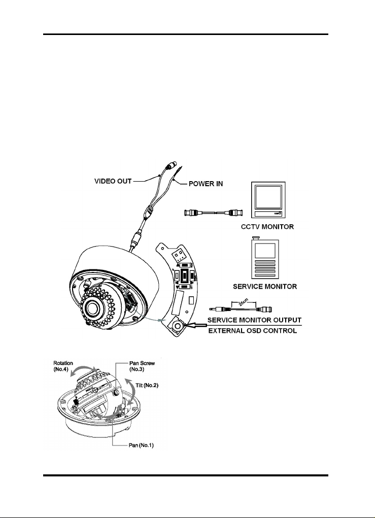
4.5. Connections
- Power connection: Requires a DC 12V or AC 24V input depending on the camera
model.
- All camera models are supplied with a service monitor output on the camera module. A
service monitor and control cable is included in the package.
Note:
To set up the OSD menu externally, a service monitor and control cable is required.
4.6. 3-Axis Gimbal Adjustment
1. Pan: Adjust the first pan angle by turning
the gimbal 360° degrees (see figure No.1).
2. Tilt: Adjust the tilt angle by moving the
gimbal up and down (see figure No.2).
3. Rotation: Loosen the pan screw (No.3) to
adjust the pan to a desired angle (see figure
No.4) and fix the screw.
6English
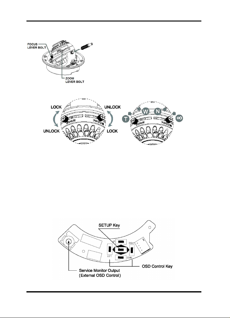
4.7. Zoom & Focus Adjustment
If you require to make viewing angle/focus
adjustments, loosen the lever bolt and
make the necessary adjustment as shown.
- Field of View: Telephoto (T) to Wide (W)
- Focus: Near (N) to Infinity (oo)
Caution:
Focus and Zoom Lever Bolts MUST be pushed back in properly. If they touch the inside
of the dome bubble, they will cause scratches. This may effect the view of the camera.
5. OSD Menu
5.1. OSD Controls
5.1.1. OSD Control Keys
- SETUP key: Accesses the menu mode or confirms the setting.
- UP (/\) / DOWN (\/): Chooses the desired menu.
- LEFT (<) / RIGHT (>): Sets up the value of the selected menu.
7English
5.1.2. OSD Icons
Exits the menu setting. Before you exit,
make sure you SAVE your settings, or
select QUIT to cancel.
Returns to the previous menu.
Returns to the main menu.
Use this to SAVE your settings of MASK
AREA, PRIVACY ZONE and more. Once
you saved your settings, they will remain
even if you select QUIT in the menu.
Use this to delete your settings of MASK
AREA, PRIVACY ZONE and more. Once
you saved your settings, they will not be
restored even if you select QUIT in the
menu.
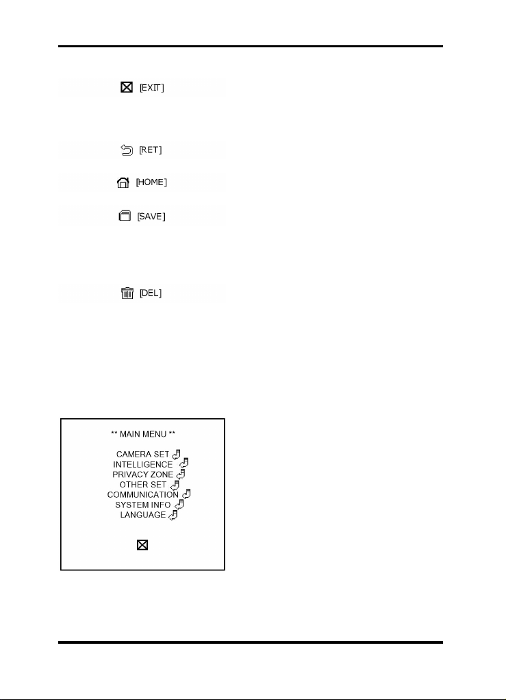
5.2. Main menu
1. Press the SETUP key and hold it for a while to access the menu mode.
2. Select the desired feature by using the UP/DOWN keys (/\ \/) on the control.
CAMERA SET: Here you can configure
camera related functions and data.
INTELLIGENCE: You can configure the
settings of motion detection, tracking and
more.
PRIVACY ZONE: You can configure the
privacy related settings.
OTHER SET: You can configure for factory
defaults, and more.
8English
Ce manuel convient aux modèles suivants
4
Table des matières
Autres manuels Grundig Caméra dôme


