Grozone Control sLS24 Manuel utilisateur

USER GUIDE
sLS24
Smart Light Switcher
With High Temp Shut-Off
www.grozonecontrol.com

WARNINGS & CAUTION 3
GENERAL DESCRIPTION 4
SPECIFICATIONS 5
INSTALLATION GUIDE 6-7
TROUBLESHOOTING GUIDE 8-9
WARRANTY & CUSTOMER SERVICE 10-11
TABLE OF CONTENTS

· Read all instrucons before operang the sLS24
· This light switcher is designed to work with electronic and
magnec ballasts
· Protect your sLS24 against water or any sprayed products
· Mount your sLS24 securely to the wall using included
hardware
· Do not aempt to repair the sLS24 yourself, call Grozone
Control technical support 1-855-262-1800
· Make sure to verify your electrical panel components and
capacity prior to wiring your sLS24 into the power source
· Plug in 240 V loads only
FOR SUPPLY CONNECTIONS, USE 1/0 AWG OR LARGER
WIRES SUITABLE FOR AT LEAST 75°C (167°F). USE
COPPER WIRE ONLY.
WARNING & CAUTIONS
3
THIS PRODUCT MUST BE INSTALLED BY A
LICENSED ELECTRICIAN ONLY

The sLS24 Smart Light Switcher is specifically designed to operate a
high intensity discharge (HID) lighng systems. The system can han-
dle up to a maximum of 24 1000 wa HID metal halide (MH) or
high pressure sodium (HPS) grow lights. The acvaon of the inter-
nal power switches (relays) is performed through 120V trigger in-
put. The sLS24 can control 24 lights with one single trigger input.
This Smart Light Switcher provides up to 120 amps of capacity on a
standard 240 volts circuit. The sLS24 integrates a high temperature
shut-off funcon that turns off 1, 2 or 3 of the 6 zones if room tem-
perature goes above the preset temperature limits. sLS24 provides
2 remote temperature sensors (to improve safety, the 2 sensors
are unlikely to fail at the same me) and 2 PCB-mount slide switch-
es to acvate high temp shut-off and set temperature limits. Refer
to page 7 for more informaon. The sLS24 is built with only the
highest quality components and will provide you with years of trou-
ble free performance.
GENERAL DESCRIPTION
4

· Number of lights : total of 24 lights, 6 zones of 4 lights.
· Number of 120V trigger input: 1
· Light receptacles: NEMA 6-15 (240V 15A), 12 duplex
receptacles for 24 lights, 12 lights on each side.
· Metal enclosure dimensions: 28 in. X 21.5 in. X 3 in.
(H x W x D)
· Circuit breakers: total of 12 double breakers (240V, 15A)
1 double breaker for two lights. Breakers meet UL 489.
· Input power requirement: 240V 125A 60Hz.
· ETL Listed per CSA/UL Standards.
SPECIFICATIONS
5
IMPORTANT: THIS PRODUCT MUST BE INSTALLED BY A
LICENSED ELECTRICIAN ONLY
1. Secure the sLS24 to the wall using the included hardware
(#8 wood screws in round holes on top and boom flanges).
2. Unscrew the 8 cover screws.
3. Use the correct size wire for your applicaon. Please check local electrical
codes for wire size requirements. Carefully strip the 2 power wires ap-
proximately 1’’. Pass the stripped and copper wires through the largest
strain relief located on boom wall of enclosure.
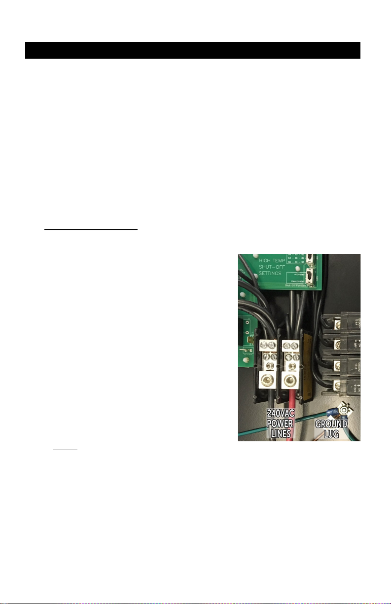
Hook up 240V wires as follows:
· Black wire on le Hex screw
· Red or White wire on right Hex
screw
· Copper wire to GROUND LUG lo-
cated near the power terminal
block (boom right, near breaker
screw terminals).
IMPORTANT NOTICE:
Power Terminal Block : loosen terminal screws using a 3/16 Hex key,
insert wires as shown then ghten up screws
and wire connector (strain relief).
INSTALLATION GUIDE
4. sLS24:
Acvate and set high temperature limits
sLS24 High Temperature Shut-Off Operaon :
In order to maintain the room temperature below the preset tempera-
ture limit ranges, the sLS24 may need to turn off 1, 2 or 3 zones, each
zone comprising 4 lights. To ensure an even distribuon of the light in
your grow room, the sLS24 features smart zone rotaon that changes
the OFF zone(s) from zone 1 to zone 6 alternately.
6

Each preset High Temperature Limit range is made up of 3 values:
· When room temperature reaches the 1st value, only 1 zone will turn off.
· If room temperature reaches the 2nd value, a second zone will turn off.
· Finally, if room temperature reaches the 3rd value, a third zone will turn
off.
NOTE : when a high temp condion is met, turning 1 zone OFF should enable room tempera-
ture to return to normal condion. Turning 2 or 3 zones OFF may occur when cooling equip-
ment or outdoor temperature reach extreme condions. In the worst case (3 zones OFF), there
will always be a minimum of 3 zones with the lights ON to maintain the photoperiod in your
grow room.
Replace cover and ghten up screws.
Do not over ghten to prevent screw thread stripping .
INSTALLATION GUIDE
slS24 provides 3 different High Temperature Limit ranges:
use upper slide switch (SW1) to select your preferred range.
· High Temp Limit range 1:
- 1st zone turns OFF when temp. reaches 27°C / 80°F
- 2nd zone turns OFF when temp. reaches 28.5°C / 83°F
- 3rd zone turns OFF when temp. reaches 30°C / 86°F
· High Temp Limit range 2:
- 1st zone turns OFF when temp. reaches 28.5°C / 83°F
- 2nd zone turns OFF when temp. reaches 30°C / 86°F
- 3rd zone turns OFF when temp. reaches 31.5°C / 89°F
· High Temp Limit range 3:
- 1st zone turns OFF when temp. reaches 30°C / 86°F
- 2nd zone turns OFF when temp. reaches 31.5°C / 89°F
- 3rd zone turns OFF when temp. reaches 33°C / 92°F
Maximum OFF period: the zone rotaon funcon ensures that OFF periods never
exceed 1 hour per zone.
Minimum OFF period: to prevent hot start, OFF periods last a minimum of 20 minutes, even
though room temperature has cooled down below limits in less than 20 minutes.
Acvang / Deacvang the High Temp Shut-Off operaon:
Lower slide switch (SW2) is used to ACTIVATE or DEACTIVATE the High Temp Shut-Off funcon.
Once deacvated, the sLS24 operates as any standard trigger-cord acvated light controller
and the temperature probes are not read.
Note: middle switch posion is “ACTIVATED” as top posion.
7

Problems Actions
The lights will not
turn on
Verify that there is power to the 120V
trigger input. You will hear a loud “click”
caused by relay switching when power
is applied to the trigger input.
Check if the main circuit breaker and
the sLS24 breakers are in the ON
posion, and reset them if necessary.
Verify that the unit is wired properly.
Put the switch SW2 in posion deac-
vated.
Check with a licensed electrician if there
are any concerns regarding proper in-
stallaon of your sLS24.
There is no power on
one side of your sLS24
(1, 2 and 3 zones on
the le side, 4, 5 and 6
zones on the right
side)
Check if the corresponding sLS24
breakers have tripped. The breaker
actuator must be firmly engaged in the
ON posion .
Put the switch SW2 in posion deac-
vated.
TROUBLESHOOTING
8

Problems Actions
The main circuit breaker
keeps tripping.
Check the main circuit breaker in
the electrical panel, the breaker
value must be at least 150A to
meet most of North-American
electrical codes. Please consult
with a licensed electrician.
Sll having problem with your sLS24?
Please contact Grozone Control Technical Support at
1-855-262-1800 or by email service@grozonecontrol.com
TROUBLESHOOTING
9

DO YOU HAVE A PROBLEM WITH YOUR sLS24 ?
PLEASE READ THESE INSTRUCTIONS CAREFULLY
AND SAVE THEM FOR FUTURE REFERENCE
1. I think my sLS24 is damaged, or it simply does not work
as indicated in the user guide, what should I do?
· Please refer to the troubleshoong steps. Follow these in-
strucons carefully, step by step. The sLS24 should work as
described in the “Acons” column of the Complete Trouble-
shoong Guide.
Do you need assistance on execung the Troubleshoong steps?
1. Contact us at 1-855-262-1800
2. Send us an EMAIL at [email protected] or
3. VISIT our Technical Support Center at
www.grozonecontrol.com/techsupport.html
Technical Support is available Monday through Friday,
from 8:00 AM to 8:00 PM, Eastern Time.
WARRANTY & CUSTOMER SERVICE
10
Table des matières
Langues :
Autres manuels Grozone Control Changer


