Granite River Labs GRL-USB-PD-A1 Manuel utilisateur

User Manual for GRL USB Type C Power Delivery
Performance Analyzer
(GRL-USB-PD-A1)
This material is provided as a reference to install Rev 1.07.03 of Granite River Labs (GRL)
USB-PD Type-C™ Power Delivery Performance Analyzer A1 Software.
For software support, contact [email protected].

Table of Contents
Table of Contents ................................................................................................................................ 2
1 Overview .............................................................................................................................................. 4
1.1 Features ........................................................................................................................................ 4
1.1.1 Voltage and Current of VBUS / CC1 / CC2 Signal Analysis ..................................................... 4
1.1.2 Power Delivery Message Decode ........................................................................................... 5
1.2 Connection image ......................................................................................................................... 6
1.3 Power Delivery Protocol Analysis View......................................................................................... 6
2 Revision Record .................................................................................................................................... 6
3 Specification ......................................................................................................................................... 7
3.1 Supported USB Type-C ™ / Power Delivery Standard ................................................................... 7
3.2 USB Type-C ™ VBUS / CC / VONN signal monitoring function ...................................................... 7
3.3 GRL-USB-PD-A1 Analyzer Dimensions and Weight ....................................................................... 7
3.4 GRL-USB-PD-A1 Analyzer Electrical specifications ........................................................................ 7
3.5 GRL-USB-PD-A1 Analyzer Environment specification ................................................................... 7
3.6 GRL-USB-PD-A1 Analyzer Protocol Analysis Host PC Operating Environment ............................. 7
4 Set Contents ......................................................................................................................................... 8
4.1 Hardware components ................................................................................................................. 8
4.2 Software Components .................................................................................................................. 8
5 Appearance .......................................................................................................................................... 8
5.1 USB Type-C ™ Plug connector ....................................................................................................... 8
5.2 USB Type-C ™ Receptacle connector ............................................................................................ 8
5.3 USB Micro-B connector ................................................................................................................. 8
5.4 Status Indicator LED ...................................................................................................................... 9
5.4.1 LED State Description ............................................................................................................. 9
6 Installation method .............................................................................................................................. 9
6.1 Connection of GRL-USB-PD-A1 Analyzer to Control PC ......................................................... 9
6.1.1 Connection diagram for the software installation ................................................................. 9
6.2 GRL-USB-PD-A1 Analyzer Driver Installation ........................................................................... 9
7 GRL-USB-PD-A1 Protocol Analyzer Application Usage ....................................................................... 11
7.1 Launching the GRL-USB-PD-A1 Application ................................................................................ 11
7.2 Start Capture ............................................................................................................................... 11
7.3 Record Settings ........................................................................................................................... 11
7.4 VBUS Current Direction Setting .................................................................................................. 12
7.5 Save Setting of Capture File ........................................................................................................ 12
7.6 Capture File Setting Details ......................................................................................................... 13

8 Operation method ............................................................................................................................. 14
8.1 Connection diagram .................................................................................................................... 14
8.2 Start GRL-USB-PD-A1 Application ............................................................................................... 14
8.3 Capture Start Operation.............................................................................................................. 14
8.4 Capture Stop operation .............................................................................................................. 15
8.5 Clear Capture Data ...................................................................................................................... 15
8.6 Analysis of Capture Data ............................................................................................................. 15
9 Feature Description ........................................................................................................................... 15
9.1 PD Message-Column Settings ..................................................................................................... 15
9.2 Operation screen ........................................................................................................................ 16
9.3 Description of Various Tool bars ................................................................................................. 17
9.4 Present VBUS / CC1 / CC2 voltage / Current Status Indication ................................................... 17
9.5 PD Message List .......................................................................................................................... 18
9.6 PD Message Find Operation ........................................................................................................ 19
9.7 PD Message -Auto Scroll ............................................................................................................. 19
9.8 PD Message- Display Filter Setting ............................................................................................. 20
9.9 PD Message-Font Setting ............................................................................................................ 21
9.10 File Export Operation ................................................................................................................ 21
9.11 PD Message Time Stamp Feature ............................................................................................. 23

1 Overview
GRL-USB-PD-A1 can be used to analyze behavior between any USB Type-C based device
like Apple Mac’s, Chromebooks and Android phones, Thunderbolt 3 docks, DisplayPort
adapters, Qualcomm Quick Charge AC adapters, USB PD power banks, Cable E-Markers, etc.
Using passive adapters, the GRL-USB-PD-A1 can also check for power and USB Power
Delivery protocol communication over Apple Lightning connectors, and analyze charging
behavior over USB micro-B and Type-A connectors.
GRL-USB-PD-A1 Analyzer connected between two USB Type-C ™ devices captures the
voltage / current information of the VBUS / CC / VCONN signals exchanged between the USB
Type-C ™ devices. The captured data is transmitted to the control PC connected to the USB
Micro-B port. The GRL-USB-PD-A1 software decodes the captured data and gives a graphical
representation of the voltage and current signals captured.
USB Type-C ™ and USB-C ™ are trademarks of USB Implementers Forum.
1.1 Features
1.1.1 Voltage and Current of VBUS / CC1 / CC2 Signal Analysis
The VBUS / CC1 / CC2 signal can be measured to the precision of 1 millisecond accuracy.
The software performs a detailed analysis of Power Delivery message, VBUS voltage and
Current change.

1.1.2 Power Delivery Message Decode
The contents of the captured PD messages are displayed in detail in accordance with the USB
PD Specification.

1.2 Connection image
1.3 Power Delivery Protocol Analysis View
The image below shows the detailed view of PD Message decode and corresponding CC-Line, VBus
and Current measurement.
2 Revision Record
Version Revision
Date
Description of Changes Author(s)

3 Specification
3.1 Supported USB Type-C ™ / Power Delivery Standard
Universal Serial Bus Type-C ™ Cable and Connector Specification Revision 1.2
Universal Serial Bus Power Delivery Specification Revision 2.0, V1.2
Universal Serial Bus Power Delivery Specification Revision 3.0, V 1.0a
Universal Serial Bus Power Delivery Firmware Update Specification Revision 1.0
Universal Serial Bus Type-C ™ Authentication Specification Revision 1.0
VESA DisplayPort Alt Mode on USB Type-C Standard Ver.1.0a
3.2 USB Type-C ™ VBUS / CC / VONN signal monitoring function
Corresponding VBUS voltage: 0 to 20.0 V (resolution about 10 mV)
Corresponding VBUS current: 0 to 5.0 A (resolution about 1 mA)
Corresponding CC 1 / CC 2 voltage: 0 to 5.0 V (Resolution about 10 mV)
Corresponding CC 1 / CC 2 current: 0 to 1.2 A (resolution about 1 mA)
Sampling cycle: Approximately 1 to 1000 ms (can be specified by application)
3.3 GRL-USB-PD-A1 Analyzer Dimensions and Weight
External dimensions: W 21.8 X L 61.6 X H 8.3 ± 0.2 mm
Mass: 16 g
3.4 GRL-USB-PD-A1 Analyzer Electrical specifications
· Supply voltage: DC + 5.0V ± 10%
· Device consumption current: 32.0 mA (Typical value during operation)
3.5 GRL-USB-PD-A1 Analyzer Environment specification
· Operating temperature range: 5 ~ + 40 ℃
· Operating humidity range: 35 to 85% RH (with no condensation)
· Restriction on the use of hazardous substances: REACH, RoHS
3.6 GRL-USB-PD-A1 Analyzer Protocol Analysis Host PC Operating Environment
Supported PC: Windows® PC with USB host
Supported OS: Windows® 7/8 / 8.1 / 10 (32 bit / 64 bit)
Hard disk for saving captured data, mouse, keyboard, display mounted mandatory

4 Set Contents
4.1 Hardware components
GRL-USB-PD-A1 Analyzer body
USB cable connecting controller to the host PC is not included in the product. Please
prepare separately.
4.2 Software Components
GRL-USB-PD-A1 Analyzer application executable file "· USB-PD-A1.exe"
GRL-USB-PD-A1 Analyzer Instruction Manual (this book)
Please download the latest software from the following link
http://graniteriverlabs.com/usb-type-ctm-power-delivery-performance-analyzer-grl-usb-pd-a1/
5 Appearance
5.1 USB Type-C ™ Plug connector
To connect a USB Type-C ™ device that performs PD protocol analysis.
5.2 USB Type-C ™ Receptacle connector
To connect a USB Type-C ™ device that performs PD protocol analysis.
5.3 USB Micro-B connector
To connect the control PC for GRL-USB-PD-A1 Analyzer viewer.
USB Type C Port
USB Micro B Port

5.4 Status Indicator LED
5.4.1 LED State Description
6 Installation method
Download the GRL-USB-PD-A1 software installer from the below link to the Control PC.
Double click the installer and follow the screen instructions to complete software installation.
Ensure to have sufficient space on the hard disk.
6.1 Connection of GRL-USB-PD-A1 Analyzer to Control PC
Please connect the micro-B USB port of GRL-USB-PD-A1 Analyzer to the USB port of
Control PC with USB cable.
6.1.1 Connection diagram for the software installation
6.2 GRL-USB-PD-A1 Analyzer Driver Installation
When connecting for the first time, installation of the driver is necessary. Follow the procedure
below to install driver on control PC.
LED State Description
Both OFF
□ □ No VBUS is detected or VBUS is less than 1V.
Blue ON
Green OFF
♦ □
VBUS is detected as more than 1V.
VBUS current more than 10mA flows from Receptacle -> Plug.
Blue OFF
Green ON
□♦
VBUS is detected as more than 1V.
VBUS current more than 10mA flows from Plug -> Receptacle.
Both ON
♦ ♦
VBUS is detected as more than 1V.
Less than 10mA flows on VBUS.
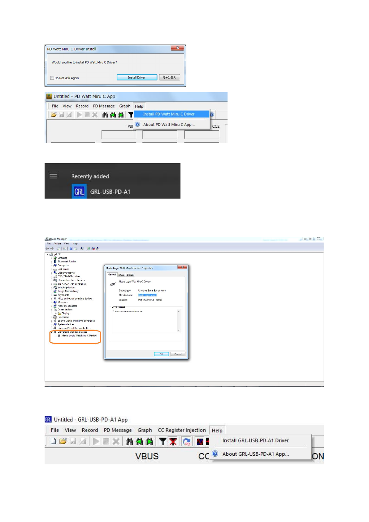
Select the GRL-USB-PD-A1 application from the windows menu as shown below.
Automatic installation of GRL-USB-PD-A1 driver will start. If the driver is successfully
installed, "Media Logic Watt Miru C Device" will be displayed in "Universal Serial Bus
Devices" of Device Manager.Device manager screen at driver installation successfully.
In the case when the driver is not installed select “Install GRL-USB-PS-A1 Driver” from the
help menu to install the driver.
Table des matières
Manuels Instrument de mesure populaires d'autres marques


Endress+Hauser
Endress+Hauser Proline Promag 50 Caractéristiques techniques

Siemens
Siemens SITRANS F Coriolis FCT030 Manuel de la liste des pièces

KLINGER
KLINGER CMF V Series Manuel utilisateur

EXFO
EXFO FTB-2 Manuel d'exploitation et d'entretien

Keysight
Keysight M8290A Manuel utilisateur

ADTEK
ADTEK MW-5 Manuel utilisateur