Gina 2000-64K Manuel utilisateur

TM
USER'S MANUAL
Model : 2000-64K
GINAUser’sManual
GINA MODEL 2000-64K
Overview
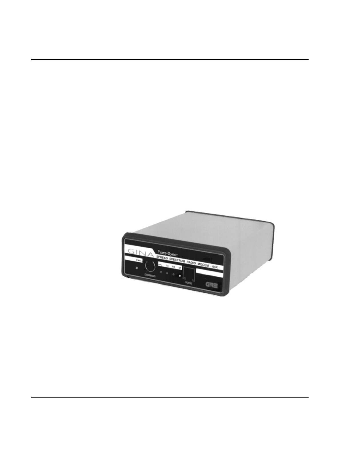
GINAModel2000-64Kisastand-alone,highfrequency data transceiver using
spreadspectrumtechnology. GINA2000-64Kcapabilitiesinclude
synchronousdata transmission atspeeds to 64Kbps at thedata port withEIA 562/
RS-232,EIA530/RS-530, andV.11(V.35) interfaces. GINA 2000-64K receives
andtransmits data inthe frequency rangeof 2.404 -2.478 Ghz atair speeds of
upto 186Kbps. Communicating atthis speedallows GINA2000-64K tobe a
full(TDD)duplexlink. GINA can beconfiguredto be usedasapoint-to-
pointcommunicationdevice.GINA2000-64Kcontainsapacketcontroller
modulewithacustomcommunicationprotocolthatprovidescommunications
handshaking,cyclicredundancychecking(CRC),packetsequencing,and
flowcontrol.
Figure6-1.GINA 64K Transceiver
Operation
ThissectioncontainoperatinginstructionsfortheGINAtransceiver,
includingcontrolsandindicators,DTErequirements,channelselection,andvoice
operation.
1-1
©1999GRE America, Inc. All rights reserved. Thismaterial is theproperty of GRE America, Inc. Copyingor re-
producing this material is strictly prohibited. All violators shall be prosecuted to the fullest extent of the law. 1/99
GINAUser’sManual
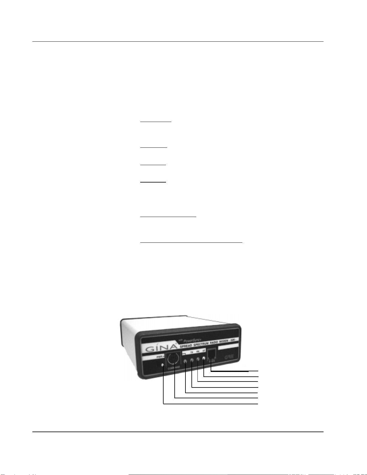
Controls and Indicators
Front Panel As shown in Figure 6-2, operating indicators, a voice handset jack, and
the command data port are located on the front panel and consists of:
1. PWR LED (Light Emitting Diode). This LED is lit when
power is applied to the transceiver.
2. TX LED. Indicates that a signal is being transmitted by GINA.
3. RX LED. Indicates a receiving condition on GINA.
4. ST LED. When green, GINA is receiving good data. When
red, data has errors, GINA is receiving bad data, or the GINA
units are not synchronizing.
5. Voice Handset Jack. Standard RJ22 telephone jack for the
GINA handset.
6. RS-232Command Control DataPort. Usedfor programming
during GINA setup. This port communicates at 9600 kbps
asynchronousonly.
NOTE: GINAonlyoperateswith the handsetsuppliedwith the unit.
Donotattemptto use a standard telephone handset.
©
1999 GRE America, Inc. All rights reserved. This material is the property of GRE America, Inc. Copying or re-producing this
material is strictly prohibited. All violators shall be prosecuted to the fullest extent of the law. 1/99
1-2
Figure 6-2. GINA Transceiver Front Panel
Voice Handset Jack
Status LED
Receive LED
Transmit LED
Power LED
GINA Setup Port
Power ON/OFF Switch

GINA User’s Manual
Rear Panel
As shown in Figure 6-3, the rear panel contains three connectors:
1. The GINA antenna jack (reverse SMA type).
2. Data Connector (DB-25).
3. 12 VDC. Power connector for the GINA AC to DC power converter.
Thecenterconnector is 12VDCpositive; the outsideisgrounded.
12 - Volt DC
Power Supply Jack
Center Pole Positive
Receiver Signal Strength
Indicator Jacks
DB25 RS-232, RS-530
or V.11/V.35 Connector
Antenna Connector
Reverse SMA Type
Figure 6-3. GINA Transceiver Rear Panel
GRE GINA Interface Board Commands
Cyclic Redundancy Check
CK=00 Disable cyclic redundancy check.
CK=01 Enable cyclic redundancy check.
Master / Slave
One radio must always be in control of the transmit and receiver timing.
MS=00 Slave
MS=01 Master(controlunit)
1-3
©1999 GRE America, Inc. All rights reserved. This material is the property of GRE America, Inc. Copying or re-producing this
material is strictly prohibited. All violators shall be prosecuted to the fullest extent of the law.
1/99

GINA User’s Manual
Data Filter Selection
FL=01 FL=02 FL=03 FL=04
Factory Set to FL=02
RF Channel Selection
Channel selection should be the same on both slave and master.
CH=01~12
Transmit Key ON
TX=00 This setting is for normal operation.
TX=01 10 sec transmit - test purposes only
Transmit Clock Selection
CS=00 Internal transmit clock
CS=01 External transmit clock
CS=02 Loop back command (slave only). This means clock
and data lines are looped back. txd=rxd, ctxc=rxc
Data Speed Selection
DR=01 9.6 Kbps Synchronous
DR=02 19.2 Kbps Synchronous
DR=03 38.4 Kbps Synchronous
DR=04 56 Kbps Synchronous
DR=05 64 Kbps Synchronous. This setting is also used to
allow asynchronous data communication
automatically at speeds of 1.2 to 19.2 Kbps.
Revision of Software
This is factory set but may be determined by checking the Display Status.
The correct settings must be used.
RV=15 1-4
©1999 GRE America,Inc. All rights reserved. Thismaterial is theproperty of GREAmerica, Inc. Copying or
re-producing this material is strictly prohibited. All violators shall be prosecuted to the fullest extent of the law.
1/99

GINA User’s Manual
Display Status
Follows any carriage return. Examples:
GINALOCAL STATUS=
CD=00 CK=00 CH=01 CS=00 DR=05 DV=01 HF=00
ID=01 IN=01 MS=01 PO=01 FL=02 RV=15 TX=00
ELAPSED SECONDS = 000000060
ERRORED SECONDS = 000000000
GINAREMOTE STATUS:
CD:00 CK:00 CH:01 CS:00 DR:05 DV:01 HF:00
ID:02 IN:01 MS:00 PO:01 FL=02 RV:15 TX:00
ELAPSED SECONDS = 000000120
ERRORED SECONDS = 000000001
Data or Voice
DV=00 Voice mode, data flow is de-activated. Voice is full-duplex
through the handset.
DV=01 Data mode, voice operation is de-activated.
Radio Transmit Hardware Flow
HF=00 Transmit and receiver are automatic.
HF=01 RTS high activates transmit and receive.
Transmit Clock Interface
IN=01 RS-232
IN=02 RS-449/V.11(.35)
This must be set in programming to operate, but specified at time of order for
hardware. Hardware is factory configured only.
1-5
©1999 GRE America, Inc. All rights reserved. This material is the property of GRE America, Inc. Copying or re-producing this
material is strictly prohibited. All violators shall be prosecuted to the fullest extent of the law. 1/99

GINA User’s Manual
Carrier Detect
CD=00 Carrier detector activates immediately every error
occurrence. This setting causes the CD line to drop
immediately if there is a dropout in the GINA to GINA
link up.
CD=01 Carrier detector holds 2 seconds every error occurrence.
This allows the CD link not to drop unless the GINA
link fade persists longer than 2 seconds.
REResetCommand
RE=01 Resets unit to factory default settings.
TWICE This command must be entered twice. The re-set must
TYPE then be followed by configuring the channel using the
CH command.
After reset:
RC=03 For 2.4 Ghz GINA
Transmitter Power Code
The Transmitter Power Code command is operational and is slated for future
product development. It should be se to 01.
01 = Full Power 03 = 6db down
02 = 3db down 04 = 20db down
RemoteStatus
Allows over the air configuration of the remote’s status. Type the command to
change and use a colon (:) instead of an equal sign (=). For example: To
change the Carrier Detect Code, type: CD:01
IdentificationCode
The ID command is non-operational and is slated for future product
development. It should be set to 01.
1-6
©1999 GRE America, Inc. All rights reserved. This material is the property of GRE America, Inc. Copying or re-producing this
material is strictly prohibited. All violators shall be prosecuted to the fullest extent of the law. 1/99

GINA User’s Manual
Frame Errors Per Second Counter
Indicates path and data integrity of the link.
ZC=00 To hide
ZC=01 To display
ZC=02 To clear and reset
Operations
1. User must confirm all commands as shown above by using a
computer connected to the command control data port at 9600
Kbps with a terminal emulation program.
2. To change a parameter, type the command letters, an “=”
symbol, and then both digits of the desired numerical value.
Example: to change the Master/Slave configuration to Slave,
type MS=00 then click on return.
3. You must set up your terminal emulation program so that it
does not automatically add a line feed (LF) after every carriage
return (CR). The only command format that works is CMD
CR not CMD CRLF.
4. Command MS has to be determined for slave or master.
5. Select RF Channel - Between 01~12 on the 2000-64K
6. The RF Channel must be the same between master and slave.
7. Select transmit clock internal or external depending on your
application.
8. When the power is turned on, the master transmits. The slave
follows the master. When you have a green LED on the ST,
you have a good quality data link between the GINA units.
When both GINA’s link, the transmit and receiver LED’s flash
continuously at approximately 10 flashes per second.
©1999 GRE America, Inc. All rights reserved. This material is the property of GRE America, Inc. Copying or
re-producing this material is strictly prohibited. All violators shall be prosecuted to the fullest extent of the law.
1/99
1-7

GINA User’s Manual
VoiceOperation
1. Both master and slave must have DV command to 00 for voice option.
Data is not active when voice is in use.
2. Connect the handsets to the RJ22 Jack (on the front of GINA) to both
the slave and master. When the voice command mode is set, you can
use the handsets to talk duplex over the link (325 to 4000Hz).
ChannelFrequency Tables
1-8
©1999 GRE America, Inc. All rights reserved. This material is the property of GRE America, Inc. Copying or re-producing this
material is strictly prohibited. All violators shall be prosecuted to the fullest extent of the law.
1/99
CHANNEL CODE SWITCH SETTINGS
FOR GINA MODEL 2000-64K
CHANNEL FREQUENCY (GHz)
1 2410
2 2415
3 2420
4 2425
5 2430
6 2435
7 2440
8 2445
9 2450
10 2455
11 2460
12 2465

GINA Users Manual
2000-64K SPECIFICATIONS
Adjacent Channel Rejection -40dB = 10MHz
Baud Rate Asynchronous 1.2 to 19.2 Kbps Duplex TDD -RS-232 (DB25F)
Baud Rate Synchronous 9.6 to 64 Kbps, Full Duplex TDD (DB25F)
Channels 12 Programmable
Control CTS, RTS, DTR, DSR, TC, RC, external TC
Data Format 8 bits, no parity, 1 stop, for command port
Dimensions (1.52H) x (4.17W) x (5.0D)
(38.6mm) x (105.9mm) x (127mm)
Dynamic Range -100 dBm ~ -30 dBm
Frequency Range 2.404 to 2.478 Ghz
Indicators PWR, TxD, RxD, DQ
Modulation Bi-Phase Shift Keying (BPSK)
PN 11 Chip
PN Rate 5. 5 MHz
Operating Mode Point -to-Point
Operating Temperature -20 to +60 Degrees C
Data Filter 4 selectable FL=01 ~ FL=04
Power Consumption 10 Watt Maximum
Power Requirements 8 to 13.8 VDC
Radio Technique Spread Spectrum Direct Sequence
Range Nominal 800+feet
Range Indoor 500 to 1500+feet
Range Outdoor 18+ Miles - Direct Line-of-Sight FCC Compliant
Relative Humidity 0-90% Non-Condensing
Systems Gain 119 dB
Transmission Delay 5mSec.
Voice Option Interface RJ22
Turn around Time 80mSec.
1-9
© 2000 GRE America, Inc. All rights reserved. This material is the property of GRE America, Inc. Copying or re-producing this
material is strictly prohibited. All violators shall be prosecuted to the fullest extent of the law.
1/2000
Weight 16 oz.
Table des matières
Autres manuels Gina Émetteur-récepteur


