GhostEye 150M V2.6 Guide produit

150M V2.6 WIRELESS HDMI/SDI
VIDEO TRANSMISSION SYSTEM
MANUAL BOOK
GHOST EYE
© 2018 Cine Gears INC. All Rights Reserved.
© 2017 Cine Gears INC. All Rights Reserved.

Trademarks
Ghost-Eye Wireless Video Transmission SystemsTM are trademarks of Cine Gears
Inc. Web Interface.
Statement of Conditions
In the interest of improving internal design, operational function, and/or reliability, Cine
Gears Inc. reserves the right to make changes to the products described in this
document without notice.
Cine Gears Inc. does not assume any liability that may occur due to the use or applica-
tion of the product(s) or circuit layout(s) described herein.
FCC Compliance Notice: Radio Frequency Notice
The device has met the FCC 15.247 requirement. In order to comply with the FCC RF
exposure requirement, the user must keep 20cm away from the antenna.
This device has been tested and found to comply with the limits for a Class B digital
device, pursuant to part 15 of the FCC Rules. These limits are designed to provide
reasonable protection against harmful interference in a residential installation. This
device generates, uses, and can radiate radio frequency energy and, if not installed
and used in accordance with the instructions, may cause harmful interference to radio
communications. However, there is no guarantee that interference will not occur in a
particular installation. If this device does cause harmful interference to radio or televi-
sion reception, which can be determined by turning the equipment off and on, the user
is encouraged to try to correct the interference by one or more of the following mea-
sures:
• Reorient or relocate the receiving antenna.
Increase the separation between the equipment and receiver.
Connect the equipment into an outlet on a circuit different from that to which the
receiver is connected.
Consult the dealer or an experienced radio/TV technician for help.
•
•
•
Information to the user
The user’s manual or instruction manual for an intentional or unintentional radiator
shall caution the user that changes or modifications not expressly approved by the
party responsible for compliance could void the user’s authority to operate the equip-
ment. In cases where the manual is provided only in a form other than paper, such as
on a computer disk or over the Internet, the information required by this section may
be included in the manual in that alternative form, provided the user can reasonably be
expected to have the capability to access information in that form.
© 2018 Cine Gears INC. All Rights Reserved.

© 2018 Cine Gears INC. All Rights Reserved.
Contents
About the 150M Wireless Video Transmission System 1
Features 1
Receiver Diagram 2
Transmitter Diagram 3
4Installation
Troubleshooting Guide
Warning 9
Specification 10
Disclaimers 11
About Cinegears 13
8

. Uses 5GHz ISM frequency band, maximum 10 frequency channels selection, coexist
with WIFI.
. Highest resolution supports color depth of up to 30 bits(10 bits/color),
. HDMI and SD/HD/3G SDI input and output, HDMI & SDI cross conversion
is supported.
. Support wireless HD video(up to 1080P 60Hz) with no compression and no delay up to
300m(984ft).
. Support point to point, and point to multi points network topology,
. Support professional audio formats include Dolby True HD, DTS-master, etc.
. AES-128 encryption with air interface HD video data stream.
. 7-36V Wide range power voltage input, compatible with most kinds of camera batteries.
. Sony F970 battery buckle, convenient for eld battery install and replacement.
. All input and output ports have +-8 kV ESD protection level(HBM,
contact discharge).
. Plug & Play – no software is required.
. Professional standard 4-pin LEMO power plugs.
. Each RX(receiver) paired to the unique TX(transmitter) in factory.
. Industrial metal and plastic case stable and reliable.
. RX built-in antenna.
. Signal indicators for wireless power status, Video status and receiver RSSI.
. The hard carrying cases provide water and shock proof to product.
© 2018 Cine Gears INC. All Rights Reserved.
Features
1

ON/OFF HDMIOUT SDIOUT
DC7-36V
LINK VIDEO
RSSI
CH
OK
Receiver :
1:Video input indicator
2:Link status indicator
3:RSSI
4:Frequency conrm button
5:Frequency selection button
1
2
3
4
5
6
8
9
10
6:Frequency display
7:SDI output
8:HDMI output
9:Power on/o
10:DC input
7
© 2018 Cine Gears INC. All Rights Reserved.
Receiver Diagram
2

CH
OK
SDIIN
HDMI IN
ON/OFF
7-36DC
VIDEO
LINK
1
2
3
4
57
8
9
Transmitter :
1:Video input indicator
2:Link status indicator
3:Frequency display
4:Frequency selection button
5:Frequency conrm button
6:SDI input
7:HDMI input
8:Power on/o
9:DC input
6
© 2018 Cine Gears INC. All Rights Reserved.
Transmitter Diagram
3
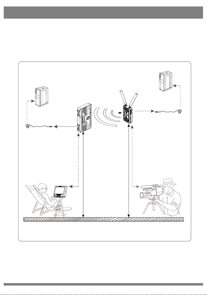
Camera
Receiver
Transmitter
Suggest installing receiver 2+ meters high from ground
Ground
Director
External Battery
Lemo Cable
Cameraman
Monitor
The best reception angel
(transmitter and receiver face-to-face)
External Battery
VIDEO OUT
VIDEO IN
Suggest installing receiver 1.7+ meters high from ground
Lemo Cable
© 2018 Cine Gears INC. All Rights Reserved.
Installation
4

© 2018 Cine Gears INC. All Rights Reserved.
1)Ensure the video source output of the camera is OK, and the HD monitor
is powered on and switched to connected video input port.
2)Ensure 2 TX antennas are installed. For optimal results set the dual
antennas in the form of a “V” and maintain unobstructed line of sight
between transmitter and receiver. Below gure for your reference.
CH
OK
VIDEO
LINK
3)Ensure all input, output SDI or HDMI cables are connected.
4)Ensure both transmitter and receiver are powered via battery or DC input.
Then turn on power switch of the transmitter and receiver respectively. The
POWER indicator will then light.
5)Ensure the transmitter and receiver is set with the same frequency.
6)If the camera is on and video input is OK, TX side VIDEO indicator will light.
Installation
5

© 2018 Cine Gears INC. All Rights Reserved.
7)Before RX nished wireless link with TX, 5 RSSI indicators and VIDEO
indicators are o; when wireless link is done, RSSI indicators will light rst
and indicate the signal strength. If the receiver detects wireless video normal
internally from air inferface, VIDEO indicator will light. Before that, If SDI or
HDMI video out port of the receiver has HD monitor connected, it will
display an OSD of Link connecting…… as in the gure below.
8) The system will spend 20-30 seconds constructing the link, depending
on link strength and the signal channel condition. When wireless link is
established the RSSI light will illuminate, indicating the current wireless
signal strength, VIDO indicators will light, and the connected HD monitor
will be playing the real-time video and audio.
Installation
Installation
6

© 2018 Cine Gears INC. All Rights Reserved.
The wireless transmission system works in the 5.1-5.9GHz frequency band
and can be exibly congured to other licensed or ISM bands to accommodate
dierent global regions. The front panel of the transmitter features a
frequency selection button (see below illustration), which provides a maximum
of 4 workable frequency channels, and supports a maximum of 4 simultaneous
receiver units.
LINK VIDEO
RSSI
CH
OK
Frequency selection button
Installation
7
Table des matières
Autres manuels GhostEye Système de microphone


Manuels Système de microphone populaires d'autres marques


Sennheiser
Sennheiser Evolution Wireless Digital EW-DX EM 2 Manuel utilisateur

Alpha Technologies
Alpha Technologies RBMS Manuel utilisateur

SWIT Electronics Co.,LTD.
SWIT Electronics Co.,LTD. CW-S150 Manuel utilisateur

Shure
Shure UA844 Manuel utilisateur

Panasonic
Panasonic SHFX70 - DVD HOME THEATER WIRELESS SYSTEM Manuel utilisateur

Pyle
Pyle PDWM5000 Manuel utilisateur