getAir LED control Manuel utilisateur

LED Control
Installation and operating instructions
V 1.1


1. General remarks....................................................................................4
1.1 Safety information...................................................................................................................... 4
2. Installation preparations......................................................................5
2.1 Contents ....................................................................................................................................... 5
2.2 Component sizes........................................................................................................................ 5
3. Installation..............................................................................................6
3.1 Electrical installation.................................................................................................................. 6
3.2 Mechanical installation.............................................................................................................. 8
4. Operating the system...........................................................................9
4.1 Control screens........................................................................................................................... 9
4.2 Operating modes and menu items ......................................................................................... 9
4.3 Further functions ......................................................................................................................10
5. Technical data .....................................................................................11
6. Disposal information..........................................................................11
7. Warranty ...............................................................................................12
8. Notes .....................................................................................................13
Table of contents

LED Control - Installation and operating instructions
4
EN
1. General remarks
This document contains the installation and operating instructions for the LED Control.
It is to be handed over to the end user (tenant, owner, building management, etc.) once
the installation has been completed. This document is part of the system and must be
kept readily available. Though its contents have been checked for consistency with the
described hard- and software, deviations cannot be ruled out, meaning that no guarantee
of complete consistency can be given. This documentation is updated on a regular
basis. Necessary corrections and useful addenda will always be included in subsequent
versions. They are also available at www.getair.eu/downloads/.
1.1 Safety information
The safety information regarding the operation and maintenance of the system contained
in these installation instructions are to be followed. Before any work is carried out on
the unit / system, the instructions and safety information are to be read carefully in full.
Non-compliance with the safety information can lead to harm/damage to persons and/
or equipment.
Assembly, electrical installation and system start-up should only be performed by skilled
persons. These are people with relevant safety training and qualied to install, commission
and label equipment, systems and cabling in accordance with current safety standards.
The following list contains descriptions of the symbols and terms used in these instruc-
tions:
Hazard symbol
Caution This hazard symbol warns about
the danger of injury.
Electricity This hazard symbol warns about
the danger of electrocution.
Warning symbol Information This warning symbol indicates im-
portant information.

Installation and operating instructions - LED Control 5
EN
2. Installation preparations
2.1 Contents
Before starting installation, please check whether all components are present, as other-
wise it will not be possible to complete the installation.
Article name Item Content Quantity
LED Control
1 LED screen 1
2 Control element 1
3 Frame 1
4 Power supply 1
2.2 Component sizes
Name Width
(mm)
Height
(mm)
Depth
(mm)
Ø
(mm)
LED screen 50 50 46 -
Control element 70 70 34 -
Frame 80 80 12.5 -
Power supply - - 32.5 53.5
1
3
2
4

LED Control - Installation and operating instructions
6
EN
3. Installation
The SmartFan is controlled via BUS cabling, meaning that cables can be laid from one unit
to the next. The maximum length of a BUS cable is 1000 m. 4-pole cables must be used.
The use of LiYY 4 x 0.25 mm² data cables is recommended.
A converter (power supply) is used to decrease voltage from 230 V to 12 V. It can supply
power to 6 SmartFan units. In larger installations, one further power supply will be needed
for each six units.
3.1 Electrical installation
All electrical work must be performed by a qualied electrician. Make sure that all wiring
is done correctly.
Control element
Power supply
rot
schwarz
+12V (4)
Bus B (3)
Bus A (2)
GND (1)

Installation and operating instructions - LED Control 7
EN
When connecting the control unit to the SmartFan unit, a
must be used. The plug must be wired as shown below. When connecting the plug to the
fan unit holder, the screws should point downwards.
When continuing the cable to a further SmartFan unit, the colours of the input and output
wires in each opening must match each other.
The LED Control can be placed at an arbitrary place within the BUS-network. It is possible
to run the cables in row, ring-shaped or also radial.
GND (1)
Bus A (2)
Bus B (3)
+12 V (4)
+12 V (4)
Bus B (3)
Bus A (2)
GND (1)
Outgoing wires
(Next SmartFan)
Incoming wires
Control
Control
Control

LED Control - Installation and operating instructions
8
EN
SmartFan fan units are equipped with a DIP switch on the top. The fan unit has to be set to
group 1 and a starting direction has to be chosen, if you are using the LED Control.
3.2 Mechanical installation
Install the control unit at standard wall height. Both the TOUCH and the LED control units
can be installed using a electronics box. The power supply can be placed in the electro-
nics box.
To avoid having to use an electronics box, you can use a DIN rail power supply instead of a
standard power supply. This can also be purchased from getAir GmbH & Co. KG. However,
such a power supply requires a further cable duct / slit for the cable to the fuse box.
A further way of avoiding the use of an electronics box is to install the power supply
behind a power socket nearby. In this case the control unit can be installed at standard
height in a single deep pattress box.
After installing the power supply (converter) and the control element, place the frame over
the control element and insert the control screen into the control element.
Group setting Fan direction
Installation and operating instructions - LED Control 9
EN
4. Operating the system
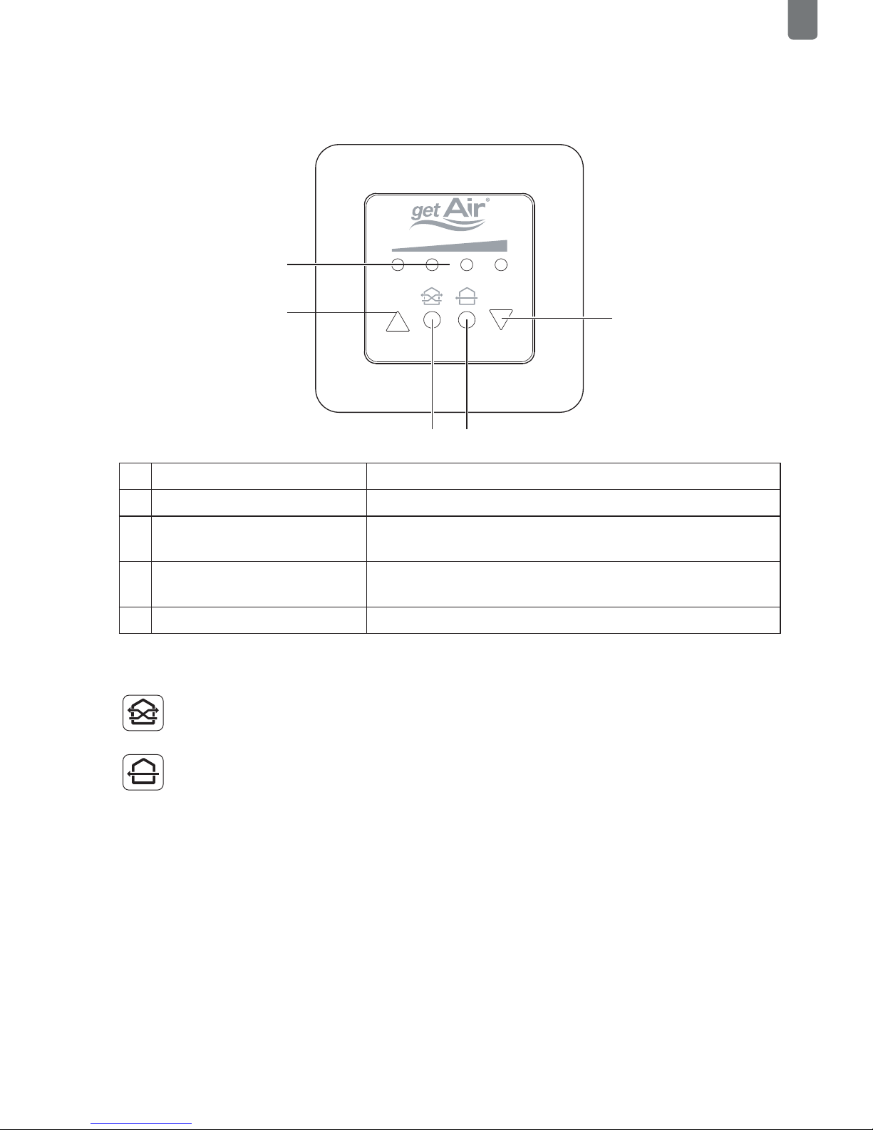
4.1 Control screens
1LEDs The LEDs show the selected fan speed.
2Arrow pointing upwards Increase fan speed.
3Eco-Mode Puts the system into heat recovery
mode. The LEDs become green.
4Full-Blast-Mode Puts the system into full blast mode.
The LEDs become blue.
5Arrow pointing downwards Decrease fan speed..
4.2 Operating modes and menu items
Every 70 seconds, the fan changes the airflow direction, ensuring heat recovery.
The system runs in just one direction, allowing a room to be thoroughly ventilated. Heat
recovery is not available in this mode. In the main menu the SmartFan‘s starting direction
can be reversed through touching the Full-Blast -Mode icon.
2
1
5
43

LED Control - Installation and operating instructions
EN
4.3 Further functions
To change the initial direction of the airflow when in full blast mode, press the left triangu-
lar button and the round button concurrently. The LEDs blink as conrmation. To reverse
the direction, press the right triangular button and the round button concurrently. Here
again, the LEDs blink as conrmation.
Filter change display
When a lter change is required, the middle two LEDs start blinking. Once the lter has
been changed, this is conrmed by pressing the two round buttons in the middle concur-
rently. In doing so, the internal meter is also reset.
Table des matières
Manuels Routeur réseau populaires d'autres marques


NETGEAR
NETGEAR FS526T - Switch Manuel utilisateur

Korenix
Korenix JetNet 5710G Series Manuel utilisateur

Automated Logic
Automated Logic ZN551 Manuel du propriétaire

Cisco
Cisco ASR 1000 Series Manuel de l'opérateur

EnGenius
EnGenius ESR-9710 Manuel utilisateur

Cisco
Cisco 805 Series Instructions d'utilisation et de sécurité