
Genius Sierra 800 Manuel utilisateur

The instructions are split into two sections: RECESS INSTALLATION, PAGE 2, and
SURFACE INSTALLATION, PAGE 6. Determine which you need before starting.
If you ordered a custom made screen skip directly to step 3.
INSTALLATION TOOLS
SCREENED PORCH • GAZEBOS • GARAGE OPENINGS
INSTALLATION INSTRUCTIONS
SIERRA 800
IT IS HIGHLY RECOMMENDED THAT THE INSTRUCTIONS BE READ THROUGH BEFORE INSTALLATION.
GENIUS SIERRA 800 INSTRUCTIONS • PART NUMBER : 50-00094-0-0-0320
PHILLIPS SCREWDRIVER MEASURING TAPE HAND-HELD OR POWER SAW POWER DRILL & BITS RUBBER MALLET
Use saw
blade suitable
for cutting
aluminum.
NEEDLE PLIERS PENCIL OR PEN

PAGE 2
SIERRA 800
RECESS INSTALLATION
J
D
F
L
KQ
Q
A
G
P
B
B
F
J
J
B
H
E
E
L
O
I
I
C
C
P
P
P
P
P
P
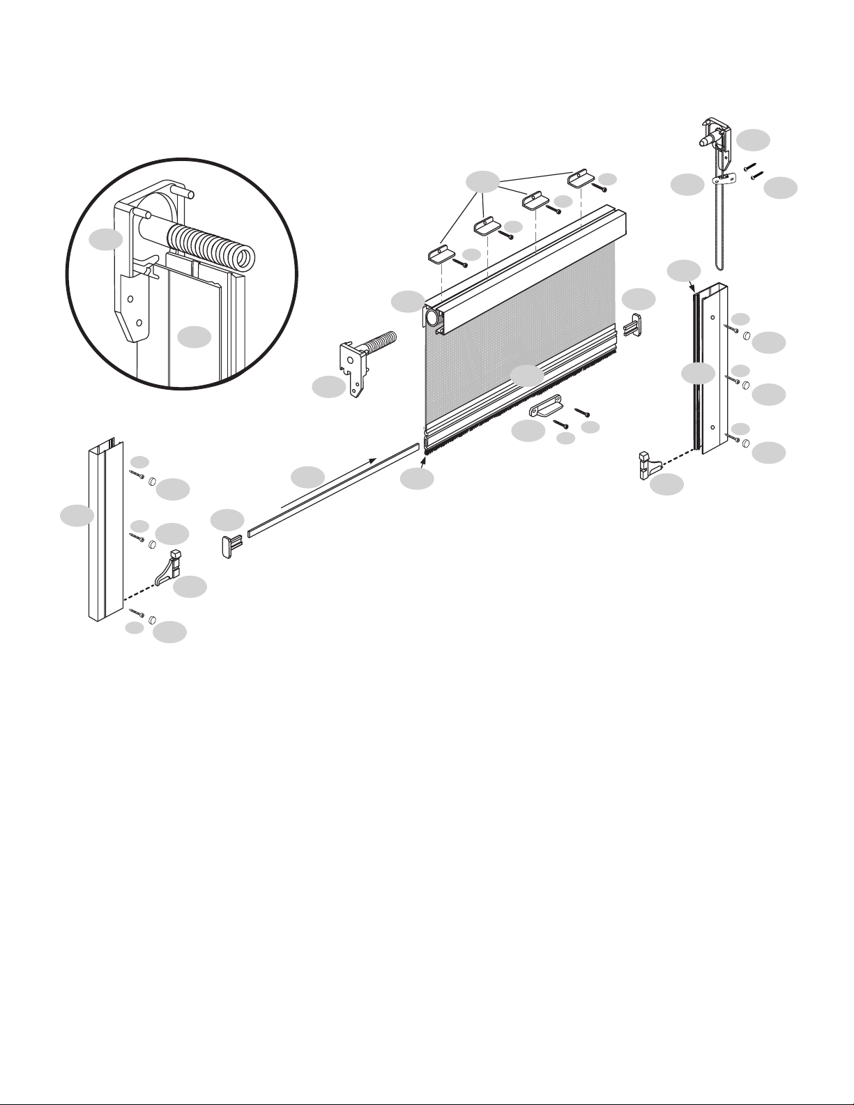
PART DESIGNATIONS
AScreen Cassette Assembly
BInside Rails
COutside Rails
DPull Bar
EPull Bar End Caps
FEnd Cap with Spring
GEnd Cap with Chain
HTension Device
IRecess Mount Clips
JWeatherstrip
KFoot Release Lever
LPull Bar Locks
OWeight Bar
P#8 x 3/4” (19mm) Panhead Screw
Q#6 x 3/8” (9mm) Phillips Panhead Screw

Record your opening measurements on the chart below to calculate your
measurements.
Cut all parts to length using the calculations above.
Keep the plastic film on the cassette until all cuts are completed.
MEASURING AND CUTTING
Determine the maximum opening height & width for mounting your
screen, as shown below. Check for interference with any door or window.
1
Width
SIERRA 800 INSTALLATION INSTRUCTIONS PAGE 3
RECESS INSTALLATION
JAMB JAMB
OPENING WIDTH
TOP VIEW
SIDE VIEW
HEAD
INSIDE
OUTSIDE
OUTSIDE INSIDE
I-RECESS MOUNT CLIP
OPENING HEIGHT
SILL or FLOOR
IMPORTANT
Be sure to make
smooth, straight cuts. Only
cut the A-Screen Cassette
Assembly on the end
without the G-End Cap with
Operating Wand.
Height
OPENING WIDTH
"
LESS 7/8" TO ALLOW
FOR END CAPS
CASSETTE LENGTH (A)
= "
OPENING HEIGHT
"
LESS 2-1/8" TO ALLOW
FOR CASSETTE END CAPS
AND RECESS MOUNT CLIPS
INSIDE & OUTSIDE RAIL
LENGTHS (B & C)
= "
– 7/8"
– 2 1/8"
If you ordered a custom made screen skip directly to step 3.

SIERRA 800 INSTALLATION INSTRUCTIONS PAGE 4
RECESS INSTALLATION
PREPARING THE SCREEN CASSETTE
Insert F-End Cap with Spring into the correct end of the A-Screen Cassette
Assembly [Fig 2A] (the assembly will only fit correctly in one end). Make sure to
line up the spring and bushing notches with one of the small slots in the center
screen tube. Wind the spring clockwise the number of turns designated in the fol-
lowing chart and push the F-End Cap with Spring in place on the A-Screen Cas-
sette Assembly. A rubber mallet is helpful to fully seat the F-End Cap with Spring.
Note that the spring in the cassette is for tension only. You will need to raise and
lower the screen by using the G-End Cap with Operating Wand.
2
3
SIDE VIEW
HEAD
OUTSIDE INSIDE
I-Recess Mount Clip
P
OPENING WIDTH
36”- 72”
73”-120”
120”-140”
140”-192”
SPRING TENSION
25
30
35
40
OPPOSITE END OF CARTRIDGE
Test Operating Wand (see page 10) for smooth operation. If it’s too tight, loosen
allen screw on the G-End Cap with Operating Wand. Insert the G-End Cap with
Operating Wand into A-Screen Cassette Assembly and push into place.
Slide one piece of the J-Weatherstrip into bottom slot of D-Pull Bar and the
other piece into the top of A-Screen Cassette Assembly. The M-Weight Bars are
already inserted inside the D-Pull Bar. Now insert the E-Pull Bar End Caps into
ends of D-Pull Bar [Fig 2B].
MOUNTING THE SCREEN CASSETTE
Mount the I-Recess Mount Clips to the inside of opening. When installed, the clips
will be centered above the cassette. Install a N-#8x3/4” (19mm) Panhead Screw
into the center of the slot to allow front to back adjustment [Fig 3].
Snap the A-Screen Cassette Assembly into place. Secure the A-Screen Cassette
Assembly in place by screwing the F-End Cap and G-End Cap to the side jamb of
the opening. The I-Recess Mount Clips and A-Screen Cassette Assembly may be
reversed to face toward the inside or outside of an opening depending upon which
side the Operating Wand needs to be accessible.
NOTE: the I-Recess Mount Clips lower the A-Screen Cassette Assembly in the
opening by 1/4”. The same 1/4” gap should be left above the F & G-End Caps to
avoid bowing the cassette.
D
A
J
J
E
E
O
F
A
2A
2B
3

SIERRA 800 INSTALLATION INSTRUCTIONS PAGE 5
RECESS INSTALLATION
FOOT RELEASE LEVER
The K-Foot Release Lever is an optional feature that makes it easier
to slightly rotate the D-Pull Bar in order to disengage the L-Pull Bar
Locks [Fig 4C] without bending over. Before installing, position the
K-Foot Release Lever 16" to 20" from the end of the D-Pull Bar on
the side closest to the Operating Wand. Attach the K-Foot Release
Lever to the D-Pull Bar using two O-#6 x 3/8” (9mm) Phillips
Panhead Screws.
6
LEFT
RIGHT
B
L
C
P
P
B
L
C
J
D
KQ
B
F
4A
4B
4C
6
Windy conditions may affect the performance of a retractable screen. Retract the
screen in windy circumstances, during inclement weather, when not needed to
support immediate ventilation or during prolong periods when not used.
INSTALLING SIDE RAILS
Install the L-Pull Bar Locks at the bottom of each B-Inside Rail. Be sure that
the L-Pull Bar Locks can engage the D-Pull Bar as shown [Fig 4C]. Slide both
C-Outside Rails onto the tabs protruding from the F and G-Cassette End Caps
[Fig 4A]. Attach to jamb with N-#8x3/4” (19mm) Panhead Screws. Press B-
Inside Rails into C-Outside Rails [Fig 4B] with the shorter pile to the inside [Fig
4D] until they are evenly seated.
Using the height adjustment wheels on the L-Pull Bar Locks, adjust the height
to the appropriate level so they easily engage the D-Pull Bar. When correctly
adjusted, the latching and unlatching should be smooth and easy.
4
Shorter Pile 4D
See page 10 for Operating Wand Instructions.
5INSTALL THE TENSION DEVICE
Go to page 10.
PAGE 6
SIERRA 800
SURFACE INSTALLATION
J
D
L
K
A
B
J
B
N
N
N
N
E
E
L
N
M
Q
Q
P
P
N
P
P
P
N
P
P
P
P
P
G
HP
F
B
F
PART DESIGNATIONS
AScreen Cassette Assembly
BInside Rails
DPull Bar
EPull Bar End Caps
FEnd Cap with Spring
GEnd Cap with Chain
HTension Device
JWeatherstrip
KFoot Release Lever
LPull Bar Locks
MSurface Mount ‘L’ Clips
NScrew Cover Caps
OWeight Bar
PP-#8 x 3/4” (19mm) Panhead Screw
Q#6 x 3/8” (9mm) Phillips Panhead Screw

Record your opening measurements on the chart below to calculate your
measurements.
Cut all parts to length using the calculations above.
Keep the plastic film on the cassette until all cuts are completed.
MEASURING AND CUTTING
Determine the maximum opening height & width for mounting your
screen, as shown below. Check for interference with any door or window.
1
Width
SIERRA 800 INSTALLATION INSTRUCTIONS PAGE 7
SURFACE INSTALLATION
GARAGE DOOR JAMB GARAGE DOOR JAMB
OPENING WIDTH
TOP VIEW
SIDE VIEW
GARAGE DOOR HEAD
OPENING HEIGHT
INSIDE
OUTSIDE
OUTSIDE
M-SURFACE MOUNT ‘L’ CLIP
SILL or FLOOR
Height
OPENING WIDTH
"
LESS 7/8" TO ALLOW
FOR END CAPS
CASSETTE LENGTH (A)
= "
OPENING HEIGHT
"
LESS 2-1/8" TO ALLOW
FOR CASSETTE END CAPS
AND SURFACE MOUNT CLIPS
INSIDE & OUTSIDE RAIL
LENGTHS (B & C)
= "
– 7/8"
– 2 1/8"
IMPORTANT
Be sure to make
smooth, straight cuts. Only
cut the A-Screen Cassette
Assembly on the end
without the F-End Cap with
Operating Wand.
If you ordered a custom made screen skip directly to step 3.

SIERRA 800 INSTALLATION INSTRUCTIONS PAGE 8
SURFACE INSTALLATION
SIDE VIEW
GARAGE DOOR HEAD
OPENING HEIGHT
OUTSIDE
M-SURFACE MOUNT ‘L’ CLIP
SILL or FLOOR
P
MOUNTING THE SCREEN CASSETTE
Slide the K-Surface Mount ‘L’ Clips into the top of the A-Screen Cassette.
The clips should be evenly spaced along the A-Screen Cassette Assembly. Make
sure cassette is level and then screw clips in place with using a P - #8x3/4”(19mm)
Panhead Screw.
3
2
OPENING WIDTH
36”- 72”
73”-120”
120”-140”
140”-192”
SPRING TENSION
25
30
35
40
3
OPPOSITE END OF CARTRIDGE (SEE PAGE 10)
Test Operating Wand for smooth operation. If it’s too tight, loosen allen screw
on the F-End Cap with Operating Wand. Insert the F-End Cap with Operating
Wand into A-Screen Cassette Assembly and push into place.
Slide one piece of the H-Weatherstrip into bottom slot of C-Pull Bar. The
M-Weight Bars are already inserted inside the hollow of the C-Pull Bar. Now insert
the D-Pull Bar End Caps into ends of C-Pull Bar [Fig 2B].
PREPARING THE SCREEN CASSETTE
Insert E-End Cap with Spring into the correct end of the A-Screen Cassette
Assembly [Fig 2A] (the assembly will only fit correctly in one end). Make sure to
line up the spring and bushing notches with one of the small slots in the center
screen tube. Wind the spring clockwise the number of turns designated in the
following chart and push the E-End Cap with Spring in place on the A-Screen
Cassette Assembly. A rubber mallet is helpful to fully seat the E-End Cap with
Spring. Note that the spring in the cassette is for tension only. You will need to
raise and lower the screen by using the F-End Cap with Operating Wand.
Remove the H-Weatherstrip from the groove at the back of the A-Screen
Cassette Assembly. This weatherstrip is not used in a surface mount
application [Fig 2A].
C
A
H
D
D
M
E
A
H
2A
2B

SIERRA 800 INSTALLATION INSTRUCTIONS PAGE 9
SURFACE INSTALLATION
J
L
B
B
N
P
N
P
L
LEFT
RIGHT
C
IO
B
F
4A
4B
6
4C
Windy conditions may affect the performance of a retractable screen. Retract the
screen in windy circumstances, during inclement weather, when not needed to
support immediate ventilation or during prolong periods when not used.
FOOT RELEASE LEVER
The I-Foot Release Lever is an optional feature that makes it easier to slightly
rotate the C-Pull Bar in order to disengage the J-Pull Bar Locks [Fig FIG 4C]
without bending over. Before installing, position the I-Foot Release Lever 16" to
20" from the end of the C-Pull Bar on the side closest to the Operating Wand.
Attach the I-Foot Release Lever to the C-Pull Bar using two O-#6 x 3/8” (9mm)
Phillips Panhead Screws.
6
INSTALLING SIDE RAILS
Install the J-Pull Bar Locks at the bottom of each B-Inside Rail. Be sure that
the J-Pull Bar Lock can engage the C-Pull Bar as shown in image [Fig 4C]. Slide
B-Inside Rails onto the tabs protruding from the E and F-Cassette End Caps, with
the shorter pile to the inside [Fig 4D]. Use an 1/8” drill bit and first drill through both
sides of the B-Inside Rails where they are to be fastened. Next, using a 3/8” bit, drill
through the outside face only. This will allow you to snap the L-Screw Cover Caps in
place. Square and attach B-Inside Rails with N-#8 x 3/4” (19mm) Phillips Pan-
head Screws. Install L-Screen Cover Caps into each hole in the B-Inside Rails.
Using the height adjustment wheels on the J-Pull Bar Locks, adjust the height
to the appropriate level so they easily engage the C-Pull Bar. When correctly
adjusted the latching and unlatching should be smooth and easy.
4
Shorter Pile 4D
See page 10 for Operating Wand Instructions.
5INSTALL THE TENSION DEVICE
Go to page 10.

SIERRA 800 TENSION DEVICE
INSTALLATION
PAGE 10
C
5
5A
5B
5C
5C
5D
5A
Plunger
A
5C
5C
5D
PARTS LIST
Chain Tension Device and #8 x 3/4 Phillips Panhead Screw
Depress the plunger with your fingers and slide the Tension Device down to the
bottom of the chain.
IMPORTANT: When mounting tension device to a wood or metal surface, provided
screws can be driven directly into the mounting surface. When mounting tension
device to drywall, use anchors or fasteners that are designed for such substrates.
Consult your hardware store, building materials retailer, or supplier for guidance
on appropriate anchors or fasteners for your substrate.
Ensure the chain is not tangled or twisted.
RECESS MOUNT INSTALLATIONS
With the narrow end up, pull down on the Tension Device until the Plunger is
compressed half way. With the Plunger compressed, place the Tension Device
against your frame as shown and make a mark through the two screw holes.
SURFACE MOUNT INSTALLATIONS
With the narrow end up, pull down on the Tension Device until the Plunger is
compressed half way. With the Plunger compressed, place the Tension Device
against your frame as shown and make a mark through the two screw holes.
If mounting to wood or metal, drill holes through your marks with a 1/8” drill
bit. Then secure the Tension Device using the provided Phillips panhead screws.
If mounting the tension device to drywall, use anchors or fasteners appropriate
for the mounting substrate and follow anchor or fastener manufacturer’s
instructions.
Autres manuels pour Sierra 800
1
Table des matières
Autres manuels Genius Écran de projection


