General VB20 Manuel utilisateur


TABLE OF CONTENTS
Introduction . . . . . . . . . . . . . . . . . . . . . . . . . . . . . . . . . 2 –3
Key Features . . . . . . . . . . . . . . . . . . . . . . . . . . . . . . . . 3 –4
What’s In the Package . . . . . . . . . . . . . . . . . . . . . . . . . . . 4
Product Overview . . . . . . . . . . . . . . . . . . . . . . . . . . . . 4 –5
Setup Instructions . . . . . . . . . . . . . . . . . . . . . . . . . . . 5 – 10
Activate Battery . . . . . . . . . . . . . . . . . . . . . . . . . . . . 5
Install Software . . . . . . . . . . . . . . . . . . . . . . . . . . 6 –8
Configure Data Logger . . . . . . . . . . . . . . . . . . . 8 – 10
Deploy Data Logger . . . . . . . . . . . . . . . . . . . . . . . . . 10
Operating Instructions . . . . . . . . . . . . . . . . . . . . . . 11 – 12
Monitoring Device Status . . . . . . . . . . . . . . . . . . . . 11
Starting & Stopping Data Logging . . . . . . . . . 11 – 12
Calibration . . . . . . . . . . . . . . . . . . . . . . . . . . . . . . . . 12
Downloading Data and Using the Software . . . . . . 12
Specifications . . . . . . . . . . . . . . . . . . . . . . . . . . . . . . . . . 13
Warranty Information . . . . . . . . . . . . . . . . . . . . . . . . . . . 14
Return for Repair Policy . . . . . . . . . . . . . . . . . . . . . . . . . 15
INTRODUCTION
Thank you for purchasing eneral Tools & Instruments’ VB10
3-Axis USB Vibration/Acceleration Data Logger. Please read this
user’s manual carefully and thoroughly before using the product.
2

The VB10 system has three components:
1. A USB memory stick (data logger) with three precision on-board
microelectronic gravitational force sensors (accelerometers).
The data logger is designed to be attached to an operating
piece of equipment (a motor, for example) and left in place to
measure and record the equipment’s acceleration in three
dimensions over an extended period of time.
2. A pedestal with magnets and screw holes for firmly mounting
the data logger to the piece of equipment.
3. A Windows-compatible graphics application that can download
thousands of stored or real-time acceleration readings to a PC
from the data logger via its USB interface. Using powerful
analysis tools in the software, an engineer or technician can
assess the health or diagnose any performance problems of the
equipment by relating the acceleration data to physical
manifestations such as vibration, motion and tilt.
KEY FEATURES
• Three accelerometers precisely measure acceleration on x, y
and z axes
• Data logger stores up to 327,600 data points in flash memory
• One button starts/stops data logging without PC
• Plug-and-play USB 2.0 interface; no need for cables, cradles or
docks
• Mounting pedestal with magnets and three screw holes
• Included PC interface/analysis software can download recorded
data or acquire real-time data or real-time frequency data
• Software is used to set system clock, operating mode (normal,
time-triggered or motion measuring), sampling rate and axial
high/low alarm thresholds
3

• Powerful analysis modes, including Fast Fourier Transform
frequency conversion and time-domain analysis
• One-click exporting of tabular data to .txt file or graph to printer
• Red and green LEDs indicate device status (recording, not
recording, battery low, memory full)
• Powered by high-capacity, long-life, non-rechargeable Li-ion
battery
WHAT’S IN THE PACKAGE
The VB10 system comes in a white box. Inside the box are:
• The USB data logging device with a pre-installed battery that
requires activation
• A mounting pedestal
• An extension cable with a full-size USB plug at one end and a
full-size USB jack at the other
• A mini-disc containing the .exe file of the Shock Software V2.1
application and a pdf explaining how to install and use it
• A hard copy of this user’s manual
PRODUCT OVERVIEW
Fig. 1 below and on the next page shows all controls, indicators
and physical structures on the data logger and pedestal.
A. Logging start/stop button
B. reen Rec LED
C. Red AmLED
D. USB plug
E. Transparent plug cap
F. Battery compartment
4
USB DA A LOGGER
F

. Locking thumbscrew
H. Data logger clamp
I. Pedestal
J. Magnets
K. Screw mounting holes
SETUP INSTRUCTIONS
ACTIVATE BATTERY
1. Use a very small Phillips-head screwdriver to remove the two
silver screws securing the grey battery compartment cover
(Fig. 1, Callout F) to the bottom of the data logger. Set the
screws aside, taking care not to lose them.
2. Carefully remove the battery compartment cover to expose the
“1/2AA” battery inside.
3. Remove the battery from the well. If the battery is covered by a
transparent plastic cover, remove and discard it. If not, proceed
to the next step.
4. Insert the battery in the well cathode (- side) first.
5. Replace the battery compartment cover and secure it with the
two silver screws.
5
PEDES AL ( OP) PEDES AL (BO OM)
K
G
H
I
J

INSTALL SOFTWARE
1. Remove the Shock Software V2.1 mini-disc from its protective
sleeve and place it in the tray of your PC’s CD/DVD drive with
the label facing up. Close the tray.
2. On the AutoPlay screen that appears next, click on “Open folder
to view files”
3. The next screen will indicate that there are two files on the
disc: <Shock Software V2.1 Instructions.pdf> and <Shock V2.1
Setup.exe>. Before installing the application, eneral
recommends that you copy the pdf to your hard drive to make
the software instructions available without having to re-load the
disc. You may also want to print out the instructions for off-line
reference.
4. Double-click <Shock V2.1 Setup.exe>. The screen below will
appear.
6

5. Click Next to call up
the screen at right.
Use the Browse
button if you want to
save the Shock
software somewhere
other than the
ProgramFiles folder.
Otherwise,
click Next.
6. On the Ready to
Insta screen at
right, click Insta .
7. While the software
installs, you will see
the screen at right.
7
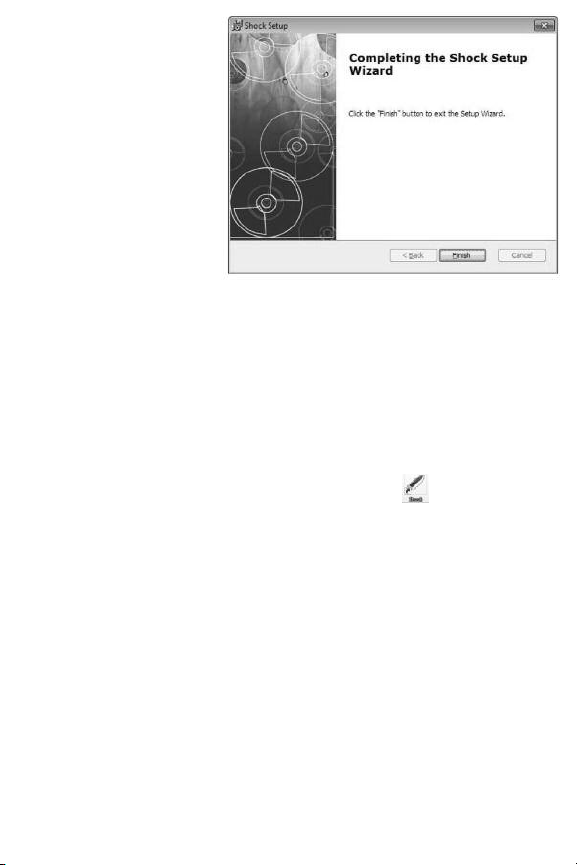
8. When installation is
complete, click
Finish to exit the
Shock Setup Wizard.
CONFIGURE DATA LOGGER
The next two steps in the setup process install a software driver
for the USB data logger, and configure the unit to your data
logging preferences.
Remove the transparent plug cap (Fig. 1, Callout E) from the data
logger to prepare it to be plugged into a USB port of your
computer.
Note that the software installation has added a icon to your
desktop. To facilitate access to the program, right-click on the
icon and pin it to both your Start button and the Quick Start area
at the left of your taskbar. You can now eject the Shock Software
mini-disc and store it with your other important software.
Plug the data logger into an available USB port of your computer.
If your computer is a laptop and the only available USB jack does
not have enough vertical clearance to accommodate the logger
without mechanically stressing its USB plug, do not plug the
logger directly into the jack. You do not want the plug of the logger
to support any of the weight of the laptop. If that is the case, plug
the data logger into the jack of the included USB extension cable
and insert the plug of the extension cable into the computer’s
USB jack.
8

The first time you plug the data logger into your computer, your
system tray will notify you that the computer is “Installing Device
Driver Software”. When the notification disappears, open the
Shock program by selecting it via your Start button, clicking on its
icon on your taskbar, or double-clicking its desktop icon.
If the software has installed correctly and you have plugged the
data logger into a working USB port of your computer, the screen
at right will
appear on your
computer’s
display.
To configure the
data ogger,
begin by selecting
the System
Parameter
pulldown of the
Fi e menu at
upper left. This
will call up the
screen at right.
9

Of all the options available on this screen, there is only one you
should initially change from the default value: Interva Time.
eneral suggests that you change this value (more commonly
called Sampling Time) from 50ms to 500ms to avoid filling up the
on-board flash memory with redundant information (nearly
identical samples taken too close together in time). Note that the
Current Time and Start Record Time fields have already been
synchronized to your PC’s clock. You can always change the other
default values later, after you have gained some experience
operating the VB10 system and the Shock software.
After you have changed the Interva Time to 500ms, click OK at
the bottom left of the screen to save the settings.
DEPLOY DATA LOGGER
To obtain accurate readings, the data logger must be securely
attached to the equipment whose vibration or motion history you
wish to log and analyze.
The data logger fits snugly in the supplied mounting pedestal. To
insert the logger in the pedestal, turn the locking thumbscrew
(Fig. 1, Callout ) to loosen it, raise the clamp (Fig. H), insert the
logger, lower the clamp over it, and turn the thumbscrew to
secure the clamp.
There are three ways to attach the pedestal and data logger to the
equipment whose acceleration is to be measured: 1) Using the
three magnets on the back of the pedestal (Fig. 1, Callout J);
2) Using screws or bolts (not included) to permanently attach the
pedestal to the equipment through the three holes in the pedestal
(Callout K); 3) luing the pedestal to the equipment.
10
Table des matières
Autres manuels General Autre


