GE VersaPoint IC220ALG221 Guide de l'utilisateur

6226B_GE 1
VERSA POINT I/O MODULE
09/2002
6226B_GE
This data sheet is only valid in asso-
ciation with the System Manual.
Function
The terminal is designed for use within an
VersaPoint station. It is used to measure analog
voltage or current signals.
Features
– Eight analog single-ended signal inputs for
the connection of either voltage or current si-
gnals
– Sensors are connected using 2-wire techno-
logy
– Various current and voltage measuring ran-
ges
– Channels are configured independently of
one another using the bus
– Measured values can be represented in five
different formats
– 16-bit analog-to-digital converter
– Process data multiplex operation
– Diagnostic indicators
Figure 1 The ANALOG IN 15 BIT VOLTAGE/
CURRENT 8CH terminalwith
connectors
Please note that the connectors are
not supplied as standard with the ter-
minal. Please refer to the ordering
data on page 45 to order the appropri-
ate connectors for your application.
6 2 2 6 A 0 0 2
6 2 2 6 0 0 0 1
ANALOG IN 15 BIT VOLTAGE/CURRENT 8CH
IC220ALG221

ANALOG IN 15 BIT VOLTAGE/CURRENT 8CH IC220ALG221
26226B_GE
Local Diagnostic Indicators and Terminal Assignment
Figure 2 The ANALOG IN 15 BIT VOLTAGE/
CURRENT 8CH terminal
with an appropriate connector
Local Diagnostic Indicators
Terminal Assignment for Each Connector
Installation Instructions
High current flowing through potential jumpers UMand UScauses the temperature of the potential
jumpers and the internal temperature of the terminal to increase. Observe the following instructions
to keep the current flowing through the potential jumpers of the analog terminals as low as possible:
All of the analog terminals need a separate main circuit.
If this is not possible in your application and if you are using analog terminals in a main
circuit together with other terminals, place the analog terminals behind all the other
terminals at the end of the main circuit.
D
A I 8 / S F
1 2
1
2
3
4
1
2
3
4
1 . 1
1 . 2
1 . 3
1 . 4
2 . 1
2 . 2
2 . 3
2 . 4
6 2 2 6 A 0 0 3
Des. Color Meaning
DGreen Bus diagnostics
Terminal
Points
Signal Assignment
1.1 +U1 Voltage input channel 1
2.1 +U2 Voltage input channel 2
1.2 +I1 Current input channel 1
2.2 +I2 Current input channel 2
1.3, 2.3 -1, -2 Minus input (for both cur-
rent and voltage)
1.4, 2.4 Shield Shield connection

ANALOG IN 15 BIT VOLTAGE/CURRENT 8CH IC220ALG221
6226B_GE 3
Internal Circuit Diagram
Figure 3 Internal wiring of the terminal points
Key:
Protocol chip Power supply unit with electrical
isolation
Optocoupler Reference voltage source
Microprocessor Analog-to-digital converter
Electrically erasable, reprogram-
mable read-only memory Amplifier
Microprocessor monitoring Multiplexer
I N T E R B U S
+ 2 4 V ( U
M
)
+ 2 4 V ( U
S
)
UL +
UA N A
UL -
E E P R O M
O P C
P
M U X
UI N 1
II N 1
1
UI N 2
II N 2
UI N 3
II N 3
UI N 4
II N 4
UI N 5
II N 5
UI N 6
II N 6
UI N 7
II N 7
UI N 8
II N 8
6 2 2 6 A 0 0 4
4
2 4 V
5 V
+-
4
44
2 2
2 2
2 2
22
R E F SUPER
OPC
xxx
XXX
R E F
P
E E P R O M
S U P E R M U X

ANALOG IN 15 BIT VOLTAGE/CURRENT 8CH IC220ALG221
46226B_GE
Electrical Isolation
Figure 4 Electrical isolation of the individual
function areas
Connection Notes
Do not simultaneously apply current and voltage signals to one input channel as you will
not obtain valid measured values.
Do not connect voltages above ±2.5 V to a current input. The electronics module will be
damaged if the maximum permissible current of ±100 mA is exceeded.
Always connect the analog sensors using shielded, twisted-pair cables.
Connect the shielding to the VersaPoint terminal using the shield clamp. The clamp con-
nects the shield directly to FE (functional earth ground) on the terminal side. Additional
wiring is not required.
Isolate the shielding at the sensor or connect it with a high resistance and a capacitor to
the PE potential.
6 2 2 6 0 0 0 5
A n a l o g i n p u t sF E p o t e n t i a l
A
B
E l e c t r i c a l i s o l a t i o n
b e t w e e n a r e a A a n d
B
U
ANA
( 2 4 V D C )
I N T E R B U S
l o c a l b u s ( I N )
I O
i n t e r f a c e
B u s i n t e r f a c e O P C a n d
m i c r o p r o c e s s o r
I N T E R B U S
l o c a l b u s ( O U T )
U
L
( 7 . 5 V D C )
U
ANA
( 2 4 V D C )
U
L
( 7 . 5 V D C )
2 4 V
5 V
+
-
5 V
+
-

ANALOG IN 15 BIT VOLTAGE/CURRENT 8CH IC220ALG221
6226B_GE 5
Connection Examples
Observe the connection notes on
page 4.
Figure 5 shows the connection schematically
(without shield connector).
Connection of Active Sensors
Figure 5 Connection of active sensors using
2-wire technology with shield
connection
The sensors have the same reference
potential.
Programming Data
1 2
1
2
3
4
1
2
3
4
1 2
1
2
3
4
1
2
3
4
1 2
1
2
3
4
1
2
3
4
1 2
1
2
3
4
1
2
3
4
D
A I 8 S F
123 4
I N
V o l t a g e s e n s o r t o
channel 1
I N
S l o t
C h a n n e l 1 2 3 4 5 6 7 8
C u r r e n t s e n s o r t
o
channel 8
ID code 5Fhex (95dec)
Length code 02hex
Process data channel 32 bits
Input address area 4 bytes
Output address area 4 bytes
Parameter channel (PCP) 0 bytes
Register length (bus) 4 bytes

ANALOG IN 15 BIT VOLTAGE/CURRENT 8CH IC220ALG221
66226B_GE
Process Data Words
Process Data Output Words for the Configuration of the Terminal (see page 7)
Process Data Input Words (see page 11)
Process Data Output Word 0 (OUT[0]) Process Data Output Word 1 (OUT[1])
Byte0Byte1Byte2Byte3
OUT[0]
(Byte.bit)
view
Byte Byte 0 Byte 1
Bit 7654321076543210
Assignment 0 Command 00000000
OUT[1]
(Byte.bit)
view
Byte Byte 2 Byte 3
Bit 7654321076543210
Assignment 000000Filter 0 Format Measuring
range
Process Data Input Word 0 (IN[0]) Process Data Input Word 1 (IN[1])
Byte0Byte1Byte2Byte3
IN[0]
(Byte.bit)
view
Byte Byte 0 Byte 1
Bit 7654321076543210
Assignment 1514131211109876543210
Depends on the command
IN[1]
(Byte.bit)
view
Byte Byte 2 Byte 3
Bit 7654321076543210
Assignment 1514131211109876543210
Depends on the command

ANALOG IN 15 BIT VOLTAGE/CURRENT 8CH IC220ALG221
6226B_GE 7
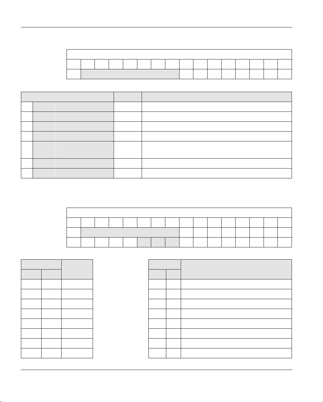
Process Data Output Words OUT[0] and OUT[1]
The terminal must be configured using the two
process data output words. The word OUT[0]
contains the command and the word OUT[1]
contains the parameters for this command.
The following configurations are possible:
–Selecting a measuring range according to
the input signal
–Selecting the mean-value generation (filte-
ring)
–Changing the formats for the representation
of measured values
Current or voltage measurement is
selected by applying the measured si-
gnal to the current or voltage input
and then configuring the measuring
range.
After applying voltage (power up) to
the VersaPoint station, the message
"Measured value invalid" (diagnostic
code 8004hex) appears in the process
data input words for every channel
scanned. The message is displayed
until the appropriate channel has
been configured.
If the configuration is changed, the
message "Measured value invalid"
(diagnostic code 8004hex) appears for
a maximum of 100 ms.
Please note the extended runtime
when a channel is configured for the
first time and every time a channel is
reconfigured.
Figure 6 Process data output words
Set all reserved bits to 0.
MSB Most significant bit LSB Least significant bit
O U T [ 0 ] O U T [ 1 ]
M S B L S B
01 4 1 3 1 2 1 1 1 0 9 8 7 6 5 4 3 2 1
C o m m a n d
1 5
M S B L S B
01 4 1 3 1 2 1 1 1 0 9 8 7 6 5 4 3 2 1
1 5
F i l t e r F o r m a t M e a s u r i n g r a n g e
6 2 2 6 A 0 0 7
R e s e r v e d ( 0 )
R e s e r v e d ( 0 0 0 0 0 0 b i n )
R e s e r v e d ( 0 0 0 0 0 0 0 0 b i n )R e s e r v e d ( 0 )

ANALOG IN 15 BIT VOLTAGE/CURRENT 8CH IC220ALG221
86226B_GE
OUT[0] (Command Code)
Bit 15 to bit 8 (command):
Bit 10 to bit 8 (channel number Z2Z1Z0or group number Y2Y1Y0):
OUT[0]
Bit 1514131211109876543210
Assignment 0 Command 00000000
Bit 15 to Bit 8 OUT[0] Command Function
00 0 0 0 Z2Z1Z00x00hex Read measured value of channel x
00 0 1 0 Z2Z1Z01x00hex Read configuration of channel x
0 0 1 1 1 1 0 03C00
hex Read firmware version and module identification
01 0 0 0 Z2Z1Z04x00hex Configure channel x
01 0 1 0 Z2Z1Z05x00hex Configure channel xand read measured value of
channel x
01 1 0 0 0 0 0 6000hex Configure entire terminal (all channels)
01 1 1 0 Y Y1Y07x00hex Commands for groups without mirroring
Z2Z1Z0Channel number
Y2Y1Y0Group number
OUT[0]
Bit 1514131211109876543210
Assignment 0 Command 00000000
Channel/group 0 X X X X X X X00000000
Code Channel Code Group
bin dec bin dec
000 0 1 000 0 4 x 8-bit group A (channel 1, 2, 3, and 4)
001 1 2 001 1 4 x 8-bit group B (channel 5, 6, 7, and 8)
010 2 3 010 2 Reserved
011 3 4 011 3 Reserved
100 4 5 100 4 2 x 16-bit group A (channel 1 and 2)
101 5 6 101 5 2 x 16-bit group B (channel 3 and 4)
110 6 7 110 6 2 x 16-bit group C (channel 5 and 6)
111 7 8 111 7 2 x 16-bit group D (channel 7 and 8)

ANALOG IN 15 BIT VOLTAGE/CURRENT 8CH IC220ALG221
6226B_GE 9
OUT[1] (Parameter Word)
The parameters for the commands 4x00hex, 5x00hex, and 6000hex must be specified in OUT[1]. This
parameter word is only evaluated for these commands.
If invalid parameters are specified in the parameter word, the command will not be exe-
cuted. The command is confirmed in the input words with the set error bit.
Bit 9 and bit 8:
Bit 6 to bit 4:
OUT[1]
Bit 151413121110 9 8 7 6 5 4 3 2 1 0
Assignment 000000 Filter 0 Format Measuring range
Code Filter (Filtering by Mean-Value Generation)
bin dec
00 0 16-sample average (default)
01 1 No mean-value generation
10 2 4-sample average
11 3 32-sample average
Code Format
bin dec
000 0 IB IL (15 bits) (default)
001 1 IB ST (12 bits)
010 2 IB RT (15 bits)
011 3 Standardized display
100 4 PIO (for the 4 mA to 20 mA range only)
101 5
Reserved110 6
111 7

ANALOG IN 15 BIT VOLTAGE/CURRENT 8CH IC220ALG221
10 6226B_GE
Bit 3 to bit 0:
The differential voltage between different terminal inputs must not exceed 50 V.
If, for example, the 0 V to 50 V range is used on one channel, the use of bipolar ranges is
not permitted on any other channel.
Code Measuring Range (Voltage)
bin dec
0000 0 0 V to 10 V (default)
0001 1 ±10 V
0010 2 0 V to 5 V
0011 3 ±5 V
0100 4 0 V to 25 V
0101 5 ±25 V
0110 6 0 V to 50 V
0111 7 Reserved
Code Measuring Range (Current)
bin dec
1000 8 0 mA to 20 mA
1001 9 ±20 mA
1010 10 4 mA to 20 mA
1011 11 Reserved
1100 12 0 mA to 40 mA
1101 13 ±40 mA
1110 14 Reserved
1111 15 Reserved
Table des matières
Autres manuels GE Système d'E/S


