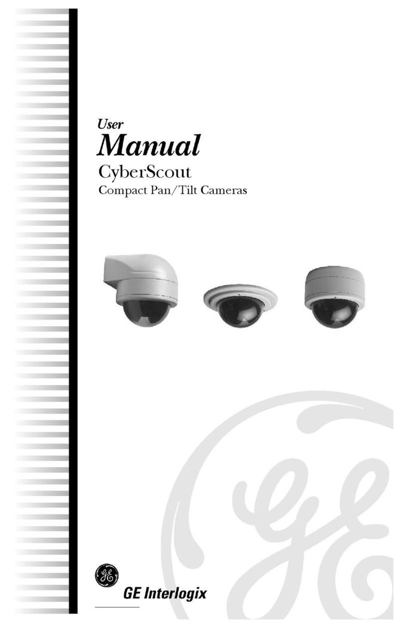
GE Interlogix KTC-510 Manuel utilisateur

KTC
-
510/515/540E B/W and
KTC-810C/815C/840CE Color
Cameras

© 2003 Kalatel, a GE Interlogix company
All Rights Reserved.
Any GE Interlogix, Kalatel division, software
supplied with GE Interlogix, Kalatel division,
products is proprietary and furnished under
license and can be used or copied only in
accordance with the terms of such license.
This document contains proprietary
information that is protected by copyright. No
part of this document may be reproduced or
transmitted in any form or by any means
without the prior written permission of GE
Interlogix, Kalatel division.
The information contained in this document is
subject to change without notice. GE
Interlogix, Kalatel division, in keeping pace
with technological advances, is a company of
product innovation. Therefore, it is difficult to
ensure that all information provided is entirely
accurate and up-to-date. GE Interlogix, Kalatel
division, accepts no responsibility for
inaccuracies or omissions and specifically
disclaims any liabilities, losses, or risks,
personal or otherwise, incurred as a
consequence, directly or indirectly, of the use
or application of any of the contents of this
document.
For the latest product specifications, visit GE
Interlogix, Kalatel division, online at
www.GE-Interlogix.com or contact your
Kalatel sales representative.
For technical support before and after installation, call 800-469-1676.
Technical support is available 24 hours a day, 7 days a week.
Call: Tech Support 800-469-1676 (6 A.M. – 5 P.M. PST Monday through Friday)
Tech Support 541-740-3589 (all other times)
Main 800-343-3358 or 541-754-9133
Fax: Tech Support 541-752-9096 (available 24 hours a day)
Main 541-754-7162
Web: www.GE-Interlogix.com
1041080A / March 2003
This equipment has been tested and
found to comply with the limits for a
Class A digital device, pursuant to part
15 of the FCC Rules. These limits are
designed to provide reasonable
protection against harmful interference
when the equipment is operated in a
commercial environment. This
equipment generates, uses, and can
radiate radio frequency energy and, if
not installed and used in accordance
with the instruction manual, may cause
harmful interference to radio
communications.
You are cautioned that any changes or
modifications not expressly approved
by the party responsible for compliance
could void the user's authority to
operate the equipment.

KTC-510/515/540C/810C/815C/840CE Table of Contents
1041080A / March 2003 3
TABLE OF CONTENTS
BEFORE YOU BEGIN................................................................4
1SETUP ..............................................................................5
1.1 SETTING THE DIP SWITCH .........................................8
1.1.1 White Balance (ATW/AWB)..........................................9
1.1.2 Backlight Compensation (BLC ON)..............................9
1.1.3 Gamma Correction (r = .45 / r = 1) ...............................9
1.1.4 Synchronization (L-LOCK/INT)...................................10
2CONNECTIONS ................................................................11
3ADDITIONAL ADJUSTMENTS .............................................12
3.1 BACK FOCUS THUMBWHEEL .....................................12
3.2 DD LEVEL (FOR DC-TYPE LENSES)...........................13
3.3 MON OUT (BNC) ..................................................13
3.4 EXTERNAL SYNC PHASE ADJUSTMENT BUTTONS .....13
TROUBLESHOOTING...............................................................14

Before You Begin KTC-510/515/540C/810C/815C/840CE
4 1041080A / March 2003
BEFORE YOU BEGIN
Read these instructions before installing or operating this product.
Note: This installation should be made by a qualified service person and should conform to
local codes.
This manual provides installation and operation information. To use this
document, you must have the following minimum qualifications:
• A basic knowledge of CCTV systems and components
• A basic knowledge of electrical wiring and low-voltage electrical
hookups
Use this product only for the purpose for which it was designed.
Customer Support
For assistance in installing, operating, maintaining, and troubleshooting
this product, refer to this document and any other documentation
provided. If you still have questions, contact Kalatel Technical Support:
GE Interlogix, Kalatel division
Call: 800-469-1676
Fax: 541-752-9096
Note: You should be at the equipment, ready with details before calling Technical Support.
Conventions Used in this Manual
Boldface or button icons highlight command entries. The following
WARNING, CAUTION, and Note statements identify potential hazards:
* WARNING:
Improper use of this equipment can cause severe bodily injury or
equipment damage.
** CAUTION:
Improper use of this equipment can cause equipment damage.
Note: Notes contain important information about a product or procedure.
* This symbol indicates electrical warnings and cautions.
** This symbol indicates general warnings and cautions.

KTC-510/515/540C/810C/815C/840CE Setup
1041080A / March 2003 5
1 SETUP
WARNING:
Do not expose the unit to moisture.
Slide out for
control panel
Mounting
threads (2) Iris lens plug
Control
panel
Iris connector Back focus
thumbwheel
Thumbwheel
locking screw
and provided
screwdriver
Figure 1. Parts of the camera
Note: Lens not included.
Note: The bracket used with the mounting threads is an option.

Setup KTC-510/515/540C/810C/815C/840CE
6 1041080A / March 2003
To set up the camera, see Figure 2 and perform the following:
Note: For back focus instructions, see section 3, Additional Adjustments.
DIP switch
Phase adjust
buttons DD level
Lens
mode
switch
Figure 2. Camera controls
1) If you are using a C-mount lens, screw on the C-mount adapter.
2) Screw the appropriate lens to the camera.
3) Set the lens mode switch
(Figure 3) to correspond
with the lens:
• For an auto iris lens
without amplifier (DC
type), set the lens mode
switch to DD.
• For an auto iris lens with
built-in amplifier (VIDEO
type), set the lens mode
switch to VD.
• For a manual iris lens, set the lens mode switch to AES.
4) If you are using an auto iris lens, insert the iris lens plug into the
auto iris lens connector. (See Figure 1.)
AES—manual iris lens
VD—video drive lens
DD—DC drive lens
Figure 3. Lens mode switch settings

KTC-510/515/540C/810C/815C/840CE Setup
1041080A / March 2003 7
Note: Figure 4 and Figure 5 show connections for the pins on the solder side of the lens
plug.
• For auto iris lens with
built-in EE amp, follow
the connections in
Figure 4. (Refer to the
lens instructions.)
• For auto iris lens without
EE amp, follow the
connections in Figure 5.
(Refer to the lens
instructions.)
NC (no
connection)
Red
(9 VAC
power)
Black
(ground)
3 White
(video)
Figure 4. Video-type auto iris lens leads
Damping
coil (+)
Damping
coil (–)
Driving
coil (–)
Driving
coil (+)
Figure 5. DC-type auto iris lens leads

Setup KTC-510/515/540C/810C/815C/840CE
8 1041080A / March 2003
1.1 SETTING THE DIP SWITCH
Set the DIP switch for your camera situation (see Figure 6 and Table 1).
Color cameras B/W cameras
Figure 6. DIP switches for color and B/W cameras
Table 1. DIP switch settings
ATW/AWB Auto-tracking white balance / auto white balance
Note: ATW/AWB is for color cameras only.
BLC ON/OFF Automatic backlight on or off
NAGC/SAGC Automatic gain control normal (30 dB) or super (36 dB)
r = .45 / r = 1 Gamma equals .45 or 1
L-LOCK/INT Line-lock or internal synchronization
FUTURE For future use (no connection)

KTC-510/515/540C/810C/815C/840CE Setup
1041080A / March 2003 9
1.1.1 WHITE BALANCE (ATW/AWB)
ATW mode (default)
In the ATW mode, the color temperature is being monitored
continuously, and the white balance is set automatically by an internal
micro-controller. The operating color temperature range is
from 2500 to 9500 K.
AWB mode
When the switch is set to AWB (conventional white balance), a camera
using white as its reference automatically adjusts the content of blue and
red in the picture, depending on the scene, to provide a picture with
balanced color content. If the color temperature of the scene is
continuously changing, the camera can lose its color reference; in this
case, switch the camera to ATW.
1.1.2 BACKLIGHT COMPENSATION (BLC ON)
This auto BLC is a digital light-level control system. It is activated
automatically by screen histogram (contrast) and 225-area window
weighting integration. This controls iris gain and white balance
simultaneously so that a clear object with adequate light level can be
optimized.
Central Window Weighted Average Backlight Compensation
This method is ideal when the main subject is fixed within the screen.
Histogram Backlight Compensation
This method is ideal when the main subject moves within the screen.
The combination of two types of backlighting makes it easier to arrange
backlight compensation operation to match the imaging conditions and
installation location.
Note: Compensation might be insufficient when the background is extremely bright.
1.1.3 GAMMA CORRECTION (r = .45 / r = 1)
Gamma correction is an electronic correction within the camera circuitry
that matches the brightness level seen by the camera with the brightness
level displayed on the monitor. This adjustment enables the monitor to
display the correct level of contrast. The standard setting is .45 (default).
The manual switch should be used only if the controls on the monitor are
not giving sufficient adjustment.

Setup KTC-510/515/540C/810C/815C/840CE
10 1041080A / March 2003
1.1.4 SYNCHRONIZATION (L-LOCK/INT)
Line-Lock (external) (default)
The sync pulses are referenced to the supply frequency. The phase
adjust buttons are used to synchronize cameras even when they are
connected to different phases of the mains supply, which results in roll-
free pictures
Internal
An internal sync generator is used when the camera is being powered off
of 12 VDC.
Ce manuel convient aux modèles suivants
2
Table des matières
Autres manuels GE Interlogix Caméra de sécurité