Garmin ONDECK GTB 10 Manuel utilisateur

ONDECK™
INSTALLATION INSTRUCTIONS
Important Safety Information
WARNING
Failure to follow these warnings, cautions, and notices could result in personal injury, damage to the vessel or
device, or poor product performance.
See the Important Safety and Product Information guide in the product box for product warnings and other
important information.
When connecting the power cable, do not remove the in-line fuse holder. To prevent the possibility of injury or
product damage caused by fire or overheating, the appropriate fuse must be in place as indicated in the product
specifications. Connecting the power cable without the appropriate fuse in place voids the product warranty.
CAUTION
To avoid possible personal injury, always wear safety goggles, ear protection, and a dust mask when drilling,
cutting, or sanding.
To avoid possible personal injury or damage to the device and vessel, disconnect the vessel's power supply
before beginning to install the device.
To avoid possible personal injury or damage to the device or vessel, before applying power to the device, make
sure that it has been properly grounded, following the instructions in the guide.
To avoid possible personal injury or damage to this device and vessel, only install this device when the vessel is
on land, or when properly secured and docked in calm water conditions.
NOTICE
For the best possible performance, the device must be installed according to these instructions.
When drilling or cutting, always check what is on the opposite side of the surface to avoid damaging the vessel.
Read all installation instructions before proceeding with the installation. If you experience difficulty during the
installation, contact Garmin® Product Support.
Contacting Garmin Support
• Go to support.garmin.com for help and information, such as product manuals, frequently asked questions,
videos, and customer support.
• In the USA, call 913-397-8200 or 1-800-800-1020.
• In the UK, call 0808 238 0000.
• In Europe, call +44 (0) 870 850 1241.
GUID-6AED2D91-1EED-4702-BB7B-92D845BF82D6 v8November 2022
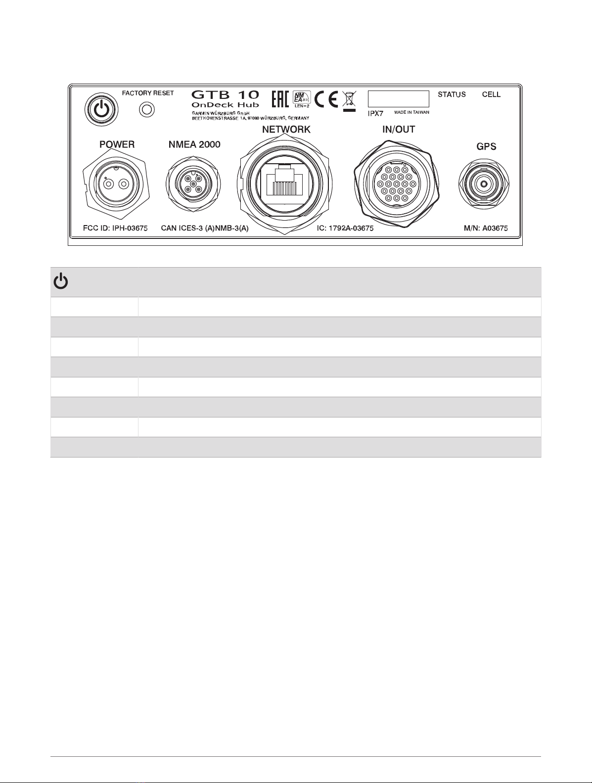
Connector View
Power button
FACTORY RESET Deletes all personal data and resets default settings
STATUS Indicates device status
CELL Indicates cell operation
POWER Power cable connection
NMEA 2000 NMEA 2000® network
NETWORK Garmin Marine Network
IN/OUT Connects relays and wired sensors, such as temperature, security, and shore power
GPS Connects to an external GPS antenna
Tools Needed
• Drill
• Drill bits appropriate for the surface and hardware
• Phillips screwdrivers
• Pencil
• Solderless wire-splice connector, or solder and heat-shrink tubing
2

Mounting Considerations
NOTICE
This device should be mounted in a location that is not exposed to extreme temperatures or conditions. The
temperature range for this device is listed in the product specifications (GTB 10 Specifications, page19).
Extended exposure to temperatures exceeding the specified temperature range, in storage or operating
conditions, may cause device failure. Extreme-temperature-induced damage and related consequences are not
covered by the warranty.
• You must mount the device in a location where it will not be submerged.
• You must mount the device in a location with adequate ventilation where it will not be exposed to extreme
temperatures.
• You must mount the device at least 102mm (4in.) from cables and other potential sources of interference.
• You must mount the device in a location that allows room for the routing and connection of all cables.
• You must mount the device with the connectors facing up when mounted on a horizontal surface or out
when mounted on a vertical surface. Do not install with the connectors facing down or facing the mounting
surface. The internal GPS antenna will not work if mounted in this orientation. See Installing the Antennas,
page4.
• For optimal internal GPS reception, you should mount the device in a location where it is above the water line
when the vessel is in the water and if possible, has a clear view of the sky.
• If you mount the device in a vessel with a metal hull or with the internal GPS antenna blocked or oriented
poorly, you must connect the device to an external GPS antenna (sold separately).
• For the best cellular signal, mount the device where it has a clear view of the sky. If it is mounted inside of a
cabin, it should be close to a window so it can receive the cellular signal.
Mounting the GTB 10 Black Box Device
NOTICE
If you are mounting the device in fiberglass, when drilling the pilot holes, use a countersink bit to drill a
clearance counterbore through only the top gel-coat layer. This will help to avoid cracking in the gel-coat layer
when the screws are tightened.
NOTE: Screws are included with the device, but they may not be suitable for the mounting surface.
Before you mount the device, you must select a mounting location, and determine what screws and other
mounting hardware are needed for the surface.
1Place the black box device in the mounting location, and mark the location of the pilot holes.
2Drill a pilot hole for one corner of the device.
3Loosely fasten the device to the mounting surface with one corner, and examine the other three pilot-hole
marks.
4Mark new pilot-hole locations if necessary, and remove the device from the mounting surface.
5Drill the remaining pilot holes.
6Secure the device to the mounting location.
3

Installing the Antennas
After mounting the device, you must orient both antennas pointing toward the sky for the best reception.
1Remove the black, rubber cap from the connector.
2Loosely attach the antenna to the connector.
3Orient the antenna toward the sky.
• If you are installing the device on a vertical surface, such as a bulkhead, you must install the antennas
parallel to the black box .
• If you are installing the device on a horizontal surface, you must install the antennas perpendicular to the
black box .
NOTE: You must have the antenna oriented properly for the cover to fit.
4While holding the antenna in the appropriate position, finger tighten the antenna nut.
5Using the included wrench, rotate the nut another 45 degrees to fully tighten the antenna nut.
The recommended torque applied to the nut is 0.56 N-m (5lbf-in.), or finger tight plus 45 degrees.
NOTICE
To ensure a water-tight connection, tighten the antenna nut to 0.56 N-m (5lbf-in.). Over tightening the nut could
cause damage to the device.
6Place the cover over the connecter.
7Secure the cover using the small screw and included #0 Phillips screwdriver.
8Repeat these steps to install the second antenna.
Connection Considerations
When connecting this device to power and to other Garmin devices, you should observe these considerations.
• You must check the power and ground connections to the battery to make sure they are secured and cannot
become loose.
• You must make sure the locking rings are tightened so the power or data connection remains secure.
• Bare wire connections must be water tight if they will be exposed to moisture. You can use heat-shrink type
butt connectors or other water-tight connections.
• To prevent corrosion of the metal contacts, you must cover unused connectors with weather caps.
• For the best connection of the GPS antenna, completely remove the weather cap from the GPS connector.
• If you need to extend the IN/OUT wires, use minimum of 24AWG (0.08mm2) wire.
• You should install a 1Amp fuse on all relay controls, Boat-in-Use, Bilge 1/2, and Battery 1/2 input wires at the
positive input to the power source.
4

Connecting to Power
WARNING
When connecting the power cable, do not remove the in-line fuse holder. To prevent the possibility of injury or
product damage caused by fire or overheating, the appropriate fuse must be in place as indicated in the product
specifications. Connecting the power cable without the appropriate fuse in place voids the product warranty.
To properly monitor your vessel when the ignition is off, you should not connect the power cable to the device
through the ignition.
Fuse (7.5 A, 42 V fast-acting)
Battery
6 ft. (1.8 m) no extension
1Route the power cable between the power source and the device.
2Connect the red power wire to the positive (+) battery terminal.
3Connect the black wire to the negative (-) battery terminal.
4Connect the power cable to the device, and turn the locking ring clockwise to tighten it.
5

Power Cable Extensions
If necessary, the power cable can be extended using the appropriate wire gauge for the length of the extension.
Splice
• Up to 4.6m (15 ft.): 10AWG (5.26mm2) extension wire
• Up to 7m (23 ft.): 8AWG (8.36mm2) extension wire
• Up to 11m (36 ft.): 6AWG (13.29mm2) extension wire
Fuse (7.5 A, 42 V fast-acting)
20.3cm (8in.)
Battery
20.3cm (8in.)
11m (36 ft.) maximum extension
6

Connection Diagram
Garmin chartplotter connected to the Garmin Marine Network and NMEA 2000 network
GTB 10 black box device
Sensor connected through the NMEA 2000 network
GPS antenna with a BNC connector (sold separately and required only if the internal GPS antenna
reception is poor)
NMEA 2000 network
Optional switch. Must be turned on for remote operation
Power source
OnDeck sensors and relays
7

IN/OUT Cable Pinout
WARNING
All connections should be made using proper electrical connectors. To avoid the potential for electric shock and
damage to equipment, ensure connections are watertight if they will be exposed to moisture.
8

Pin Number Wire Function Wire Color
Relay 1 White
Relay 2 White/orange
Relay 3 Gray
Relay 4 Pink
Relay 5 Brown
Relay 6 (Aux)1White/brown
Relay 7 (NMEA 2000) 2Blue
Shore Power White/blue
Wake (unused) Violet
Boat-in-Use White/violet
Bilge 1 White/black
Bilge 2 Red/white
Security White/green
Battery 1 Pos Red
Battery 1 Neg Green
Battery 2 Pos Yellow
Battery 2 Neg Orange
Ground (shield) Black
Temp Light green
Notes
• Each relay control wire is rated for up to 1A. External relay switches are recommended. For higher-current
loads, external relay switches are required. Do not connect these wires to the positive side of a power source.
1 This relay is automatically controlled by the GTB 10 black box device to switch power to Garmin Marine Network devices.
2 This relay is automatically controlled by the GTB 10 black box device to switch power to NMEA 2000 devices.
9

• You should install a 1Amp fuse on all relay controls, Boat-in-Use, Bilge 1/2, and Battery 1/2 inputs at the
positive input to the power source.
• The Boat-in-Use, Bilge 1/2, and Battery 1/2 inputs require a voltage between 10 and 32Vdc.
• If the boat's ground is ever intended to be switched off from the power source, do not directly connect the
Ground (black) wire from the IN/OUT wiring harness to the negative side of the of the GTB 10 black box
device's power source.
Installing the Shore Power Sensor
You can connect the AC shore power sensor to the OnDeck system to be alerted when the outlet loses power.
The shore power sensor also enables the device to stay in a full-power state when the boat is connected to
shore power.
NOTICE
To avoid damage to the sensor, you must install this sensor in a dry location.
1Select and install the proper plug type for your AC system.
NOTE: Do not plug in the shore power sensor to the power outlet at this time.
2Connect the white wire from the shore power sensor to the white/blue wire on the IN/OUT wiring harness.
3Connect the black wire from the shore power sensor to the black wire on the IN/OUT wiring harness.
4Plug in the shore power sensor to an AC outlet that is connected to the boat's shore power connection.
Installing the Temperature Sensor
1Connect one wire from the temperature sensor to the light green wire on the IN/OUT wiring harness.
2Connect the other wire from the temperature sensor to the black wire on the IN/OUT wiring harness.
3Use the ring on the temperature sensor to secure it, as needed.
You must set up the sensor in the ActiveCaptain® app.
Installing the Security Sensor
You can connect up to 30 security sensors carefully installed and tested in series.
The two parts of the security sensor should not be more than 10mm (0.4in.) apart when the door or window is
closed to engage the magnet.
1Select a location on the window or door frame and the window or door that allows the two parts of the
sensor to align.
2Use two screws to mount the wired half of the sensor to the door or window frame.
3Use two screws to mount the other half of the sensor to the door or window, ensuring that the two parts align
when the door or window is closed.
4Connect one wire from the sensor to the white/green wire on the IN/OUT wiring harness.
5Connect the other wire to the black wire on the IN/OUT wiring harness.
You must set up the sensor in the ActiveCaptain app.
10
Autres manuels pour ONDECK GTB 10
1
Table des matières
Autres manuels Garmin Changer


