GAGGLE Parade 6 Manuel utilisateur

Revisions:
D. changed model numbers, corrected spelling
error and changed to greyscale. RMK
E. Warnings update. ACN090. RMK
F. Changed name to Parade, chg’d logo
ACN92 LMH
297 mm
210 mm
1
SINCE 1954
TM
This page is for printing and document
formatting specifications only.
THIS PAGE DOES NOT PRINT
DO NOT scale the artwork for printing. Each page
has been scaled for proper scaling of parts.
Page 1 will be the cover page and first page printed
after this specification page. Any blank pages needed will
be placed at the end of the booklet.
Printer to arrange booklet pages in proper
sequence according to page number.

1
5216 Portside Dr, Medina, OH 44256 USA
• PH: 1 330.722.5033 • FAX: 1 330.722.5037
gagglestrollers.com
Gaggle®Parade™6
Models Covered: 4162077, 4162357
FOR CUSTOMER SERVICE CALL 1-877-716-2757 (outside of U.S. 330-722-5033).
DO NOT CALL RETAILER OR RESELLER FOR SERVICE AS THEY ARE NOT
AUTHORIZED TO RESOLVE ANY SERVICE ISSUES.
FOR WARRANTY AND FEDERAL SAFETY STANDARD COMPLIANCE
CERTIFICATES, PLEASE VISIT OUR WEBSITE AT
www.gagglestrollers.com
KEEP INSTRUCTIONS FOR FUTURE USE.
ASSEMBLY INSTRUCTIONS
• Adult assembly required.
• Read all instructions BEFORE
assembly and use.
• Unpack carton, remove packing
materials, safely dispose of properly or
recycle where possible.
Record product information here found on
the front frame square tube under the body.
VIN Number:
Manufacture Date:
Model Number:
For use with children whose weight is 50 lbs, (22.7 kg) or less.
Children MUST be buckled in the seats with harness properly adjusted.
AB20008F
Roof sold separately
WARNING

2
Failure to follow these warnings, assembly and maintenance
instructions could result in serious injury or death.
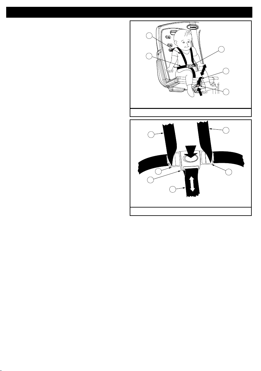
Avoid serious injury to children from falling or sliding out:
• ALWAYS use harness provided to safely hold child into seat.
• Snugly adjust harness around each child.
• NEVER leave children unattended, even when sleeping.
• Always keep children in view.
• DO NOT allow children to climb onto buggy or stand in seat.
• Always inspect harness for damage and excessive wear prior to
use. Discontinue use and replace harness immediately if
damaged.
Avoid serious injury to children:
• DO NOT allow children to sit or stand on trunk or roof.
• DO NOT place any child weighing more than 50 lbs (22.7 kg)
or taller than 45 inches (114 cm) in this buggy.
• Use caution when pushing buggy near traffic or in highly
congested areas.
• DO NOT use buggy on stairs or escalators.
• DO NOT lift buggy by push handle.
• NEVER place objects on roof.
Avoid loss of control:
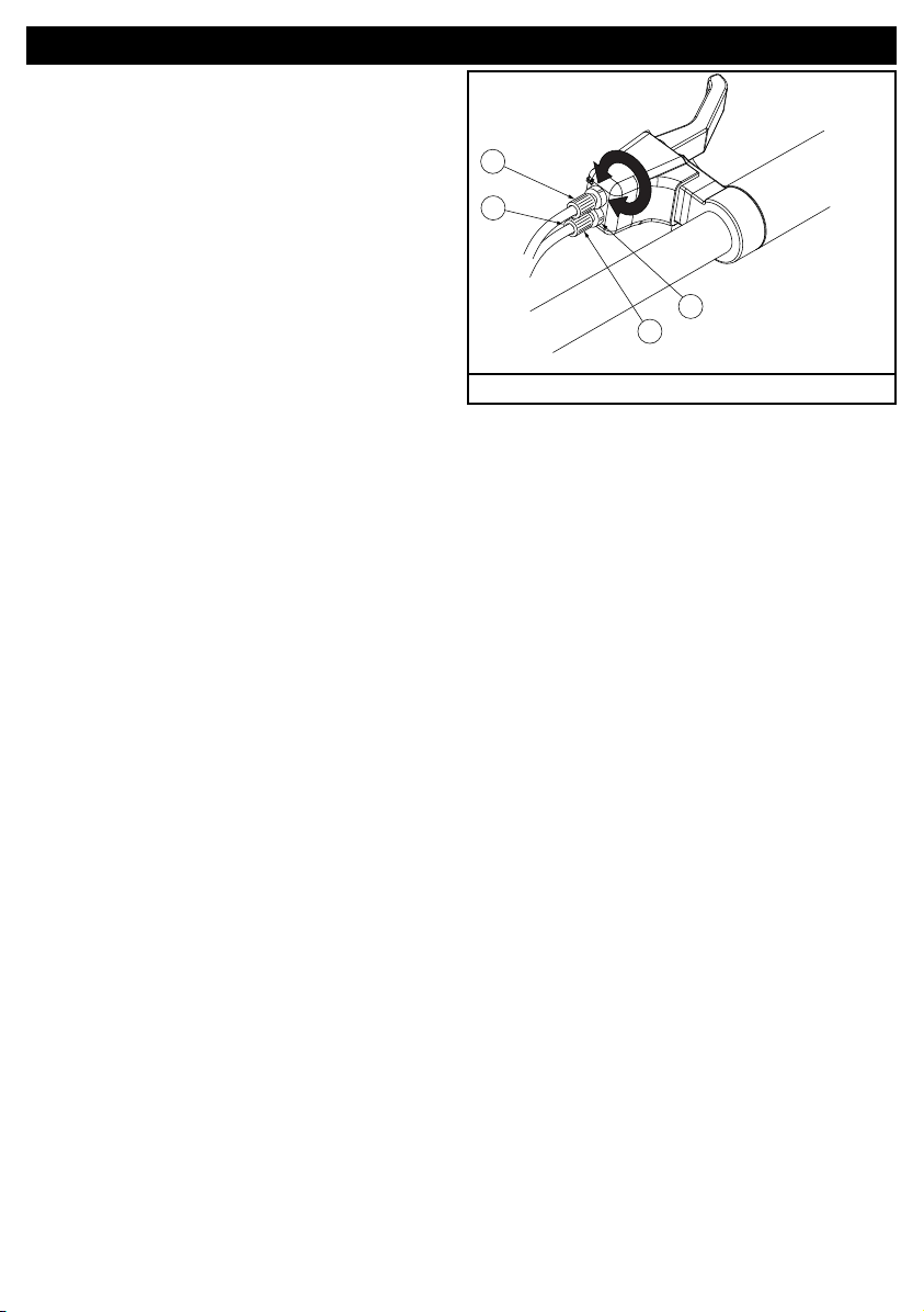
• ALWAYS use right hand Safety Control Brake when on an incline.
• Use caution when pushing buggy on uneven terrain or hills.
• ALWAYS engage left hand parking brake when buggy is stopped.
• NEVER leave buggy unattended on a hill or incline even when
parking brake is set.
Avoid injury from buggy tipping over:
• DO NOT allow children to climb into buggy unassisted.
• DO NOT allow children to play or hang on to buggy.
• DO NOT overload buggy. Excessive weight may cause a
hazardous, unstable condition to exist.
• DO NOT carry more than 6 children, one per seat, or place extra
parcels or goods in or on the buggy including roof.
• DO NOT add package carrying accessories, attach items or hang
objects from buggy as they may cause unit to become unstable.
• DO NOT place over 15 lbs. (6.7 kg) in buggy trunk.
• ALWAYS distribute weight as evenly as possible on each side of
buggy. The stroller will become unstable if the manufacturer’s
recommended load is exceeded.
Avoid pinch injury:
• Keep children’s fingers clear of trunk area, away from wheels, and
brake levers.
• When in operation or making adjustments always make sure
children’s body parts and fingers are clear of any moving parts.
WARNING

3
Gaggle Buggy and Accessories AB
C
AB20008A_G6
D
Part Description Assembly Number
A. Gaggle Buggy 416XXXX
Available as accessories:
B. Gaggle Roof Assembly 4163157
C. Gaggle Cover TBD
D. Infant Seat 4164077
Brake Operation and User Adjustment
The following Brake instructions are critical for safe operation of the
Gaggle Buggy. Brake operation MUST be conrmed before each use.
The Foundations Gaggle Buggy has a superior 2 function brake system.The Gaggle
Buggy has an control brake on the right side and a parking emergency brake on the left
side. The right side control brake is adjustable by the customer.
Right Side Control Brake Operation
AB20008A_G8
Figure 1
Brake operation:
The right side brake operation is made to be
similar to a bicycle style hand brake. The
brake is controlled by increasing pressure
as you squeeze on the handle.
This activates an ecient disc style brake.
Note: This brake handle must be free to
move in normal use. DO NOT attach any
objects to it or use any method of
restraining it’s use.
See Figure 1

4
Right Side Control Brake Adjustment
AB20008A_G9
E
F
G
H
Figure 2
Brake adjustment:
Operator must check the operation of the
brakes before each use.
If brake handle fully depresses without full
brake engagement the brakes may need
adjusted. Also, if the brakes drag when the
handle is fully released the brakes may
need adjustment.
If adjustment does not correct the handle
position or brake drag please go to Service
and Support section at foundations.com or
call customer service at 330.722.5033
The Right side disc brake is controlled by
the top cable (E) marked with an “R” on
the handle cover. The Left side disc brake
is controlled by the lower cable (F) marked
with an “L” on the handle cover.
If Handle fully depresses before the brakes
are fully engaged:
Turn the stop nut (G) counter-clockwise to
loosen assembly. Turn adjustment nut (H)
counter-clockwise 2 full turns. Tighten stop
nut (G) clockwise.
Repeat procedure for other cable.
Check to see if brake handle position
operates correctly.
if the handle still fully depresses before
brakes engage repeat the entire procedure.
If brakes drag while handle is fully released:
Turn the stop nut (G) counter-clockwise to
loosen assembly. Turn adjustment nut (H)
clockwise 2 full turns. Tighten stop nut (G)
clockwise.
If gaggle buggy pulls to one side the brake
on that side may need loosened.
If the Right side brake is dragging, the Top
brake cable (E) can be loosened 1 or 2
turns following the above procedure.
If the Left side is dragging, the lower brake
cable (F) can be loosened 1 or 2 turns
following the above procedure.
See Figure 2

5
Left Side Parking/Emergency Brake Operation
AB20008A_G10
Figure 3
Brake operation:
The Left side brake operation controls the
parking and emergency brake.
This brake handle must be free to move in
normal use. DO NOT attach any objects to it
or use any method of restraining it’s use.
The parking brake MUST be fully released
when loading occupants into or out of
buggy.
To release the brake pull the handle.
To engage the brake release the handle and
push gaggle buggy until the brake locks into
engagement.
This brake can be used as an emergency
brake as well by simply releasing the
handle.
A convenience button is provided ONLY to
be used on at surfaces.
DO NOT have button engaged when:
Loading or unloading children.
Pushing on any slope or incline.
To use the convenience button, pull
handle back, push button down and release
handle. Button will stay engaged.
To release the button pull handle slightly
and button will automatically
release.
See Figure 3
Avoid Serious injury To children From Falling or Sliding out:
•ALWAYS use harness provided to safely hold child into seat.
•Snugly adjust harness around each child.
• NEVER leave children unattended, even when sleeping.
•Always keep children in view.
•DO NOT allow children to climb onto buggy or stand in seat.
Securing Children - Harness Operation
WARNING

6
Step 1
1. Shoulder harness should be adjusted
prior to child being placed in seat. The
lowest position (1) is for a small child. The
middle position (2) is for a medium size
child. The top position (3) is for a large size
child up to 50 lbs. The shoulder belts should
be as even with the shoulders as possible.
See Figure 4
To reposition to a dierent height, Pull out
the Harness Strap Anchor (I) from the back
of the seat. Rotate the Anchor 90 degrees
and push through the seat from the back to
front.
Select the correct opening and reverse the
procedure. Pull on the strap to make sure
the anchor is seated securly.
See Figure 5 and 6
Note: Make sure both anchors are placed
into a slot at the same hieght.
AB20008A_G2
1
2
3
Figure 4
AB20008A_G11
I
Figure 5
AB20008A_12
I
Figure 6

7
Step 2
1. Secure child with harness straps by
positioning harness strap (M) between
legs and placing shoulder harness strap
(J) over shoulders and waist strap (K) over
childs thighs. Snap buckle tabs (O)
together into top of harness buckle (L).
2. To secure the child into the seat and
tighten the entire harness, pull up on the
strap (M) on the bottom of the seat.
3. To adjust the harness for looser t,
press the lever on the harness strap
adjuster (N) and release strap to desired
position
See Figure 7 and 8
M
J
K
L
N
AB20008A_G13
Figure 7
M
J
O
L
AB20008A_G14
O
J
Figure 8

8
Instructions for Roof Assembly (Purchased Separately)
X
S
U
V
W
AB20008A_G4
AB20008A_G5
P
Q
R
ST
Figure 9
The following steps 1 through 3 are to assemble and attach the Gaggle Roof Accessory
4163157 available from your Foundations authorized dealer.
Roof Assembly Step 1
To remove ller panels (X) Located in 4
places:
Pry o Cap Nut (S) with a straight blade
screw driver and discard.
Using Allen Wrench (T) remove Shoulder
Screw (U), Cap Nut Washer (V) and Plain
Washer (W).
Keep hardware (U,V,W) for re-assembly.
Pull up on 4 ller panels (X) and remove.
Filler panels must be kept for future use if
roof is not used.
See Figure10
Roof assembly:
Slide Roof Front (P) and Roof Rear (R) onto
Roof center (Q).
See Figure 9
Caution, when assembling the Roof use
caution that the center is facing up so that
clear panel does not get scratched on oor.
Part Description Part # QTY
P. Roof Front 42300025 1
Q. Roof Center 42300024 1
R. Roof Rear 42300023 1
S. Cap Nut 11300070 4
T. Allen Wrench 3/16” 11200363 1
Roof Assembly Step 2
Figure10

9
Stroller Maintenance and Care
Stroller cleaning:
• Stroller may be cleaned with a mild solution of soap and water.
• Rinse well with clear water to remove soap solution.
• Never use cleaning agents that may contain chemicals hazardous to children.
• Do not use cleaners with abrasives as this may scratch roof surface.
• Harness straps can be cleaned with soap and water and should be wiped or
air dried after cleaning.
Gaggle Parade 6 technical repair manual is available through the Gaggle Strollers web-
site. For assistance call or write:
Gaggle Strollers
5216 Portside Dr.
Medina, Ohio, 44256, USA
Telephone: 877.716.2757 (U.S.Only) or 330.722.5033
Fax: 330.722.5037
www.gagglestrollers.com
SU
V
W
B
A
AB20008A_G7
Roof Assembly Step 3
Figure 11
Attach roof:
NOTE: Foundations recommends 2 people
are needed for this step.
Place assembled roof (B) bottom tabs into
slots on top of Gaggle Buggy (A) that are
open after roof pockets were removed.
In 4 places, Place shoulder screw (U)
through cap nut washer (V) and plain
washer (W) sequentially as shown. Finger
tighten bolts.
After all 4 bolts with washers have been
inserted through roof use Allen Wrench (T)
to snug bolts but do not overtighten.
Snap on new cap nut (S).
See Figure 11.
Ce manuel convient aux modèles suivants
2
Table des matières
Langues :
Autres manuels GAGGLE Poussette


