G-Tek LM Pro T051 Manuel utilisateur

Pro
LM T051
User Programmable
Temperature Data Logger
Model No.: 99962
English/ 2023/ Rev.0.0
G-Tek Corporation Pvt. Ltd.
3, mahavir estate, karelibaug
vadodara-390 018
tel.: +91-265-2461912
email: [email protected]
url: www.gtek-india.com
OPERATING
MANUAL
LM
Pro

Page 1
CONTENTS
List of Tables .................................................................................................................... 2
List of Figures ................................................................................................................... 2
1SAFETY AND THE ENVIRONMENT ............................................................................................. 3
1.1. About this document .........................................................................................................3
1.2. Ensure Safety.....................................................................................................................3
1.3. Protecting the Environment ...............................................................................................3
2SPECIFICATIONS.................................................................................................................. 4
2.1. Use....................................................................................................................................4
2.2 Technical Data....................................................................................................................4
3 UNPACKING THE PRODUCT.................................................................................................... 7
3.1 Unpacking and Inspection of LMPro T051 Data Logger...........................................................7
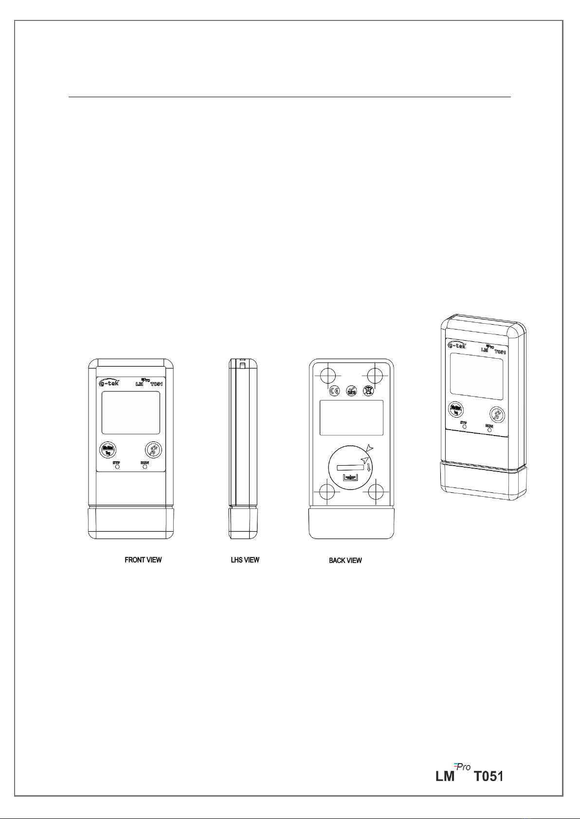
3.2 Mechanical Dimensions of LMPro T051 Data Logger ..............................................................8
4 PRODUCT DESCRIPTION........................................................................................................ 9
4.1 Status LEDs.........................................................................................................................9
4.2 Display (LCD) ......................................................................................................................9
4.3 Functions of Key ............................................................................................................... 10
5USING THE PRODUCT ......................................................................................................... 11
5.1 Configuring the Device...................................................................................................... 11
5.1.1 Alarm Configuration .....................................................................................................................11
5.1.2 Batch Configuration ......................................................................................................................12
5.2 Configure Multiple Devices ............................................................................................... 13
5.3 Batch Start of the Device................................................................................................... 14
5.4 View Min/Max and Current Temperature Data.................................................................. 14
5.5 Inserting a Tag Event......................................................................................................... 14
5.6 Displaying of Reading in Normal and Alarm Condition ....................................................... 15
5.7 Measurement of the data ................................................................................................. 16
5.7.1 Start Recording data ......................................................................................................................16
5.7.2 Tag Events ......................................................................................................................................16
5.7.3 Ending the Measurement ..............................................................................................................17
5.8 Reading out Data.............................................................................................................. 17
5.8.1 Connecting with the Software Application...................................................................................17
5.8.2 Download the Measurement Readings.........................................................................................18
5.8.3 Generating PDF Report..................................................................................................................20
6 MAINTAINING THE PRODUCT ............................................................................................... 22

Page 2
6.1 Accessories....................................................................................................................... 22
6.2 Cleaning the Data Logger .................................................................................................. 22
6.3 Changing the Battery ........................................................................................................ 22
6.4 Battery Disposal ............................................................................................................... 23
7 TIPS AND ASSISTANCE........................................................................................................ 24
List of Tables
Table 1 Technical Specifications .............................................................................................................4
Table 2 Status LEDs indication ................................................................................................................9
Table 3 Frequent Asked Questions (FAQs) ...........................................................................................24
List of Figures
Figure 1 LMPro T051 Data Logger.............................................................................................................7
Figure 2 Overall Dimensions of LMPro T051 Data Logger ........................................................................8
Figure 3 LCD Display format....................................................................................................................9
Figure 4 Set up Alarm............................................................................................................................11
Figure 5 Set up Batch ............................................................................................................................12
Figure 6 Set up Batch on Multiple devices............................................................................................13
Figure 7 Start batch manually...............................................................................................................14
Figure 8 View Min/Max and current Temperature...............................................................................14
Figure 9 Insert Manual Tag ...................................................................................................................15
Figure 10 USB Type- A connection........................................................................................................17
Figure 11 Current Temperature reading of the LMPro T051 Data Logger .............................................18
Figure 12 Selecting file location for saving data summary ...................................................................18
Figure 13 Downloaded data summary..................................................................................................19
Figure 14 Option for downloading multiple device data in existing file...............................................19
Figure 15 Multiple device data in One file...........................................................................................20
Figure 16 Filling up the options to generate PDF report ......................................................................20
Figure 17 Selecting file location for saving PDF report.........................................................................21
Figure 18 Battery replacement steps....................................................................................................23

Page 3
1SAFETY AND THE ENVIRONMENT
1.1. About this document
This instruction manual is an essential component of the product.
Please read this documentation carefully and pay attention to the safety instructions and
warning notices to prevent injuries and damage to the product.
Keep this document handy so that you can refer to it when necessary.
1.2. Ensure Safety
➢Operate the product properly, for its intended purpose and within the parameter
specified in the technical data. Using it beyond the specified limit can cause the
damage to the product and personnel also.
➢Do not use the product if there are signs of damage to the housing.
➢There are no user serviceable parts inside. For any defect, please consult the factory
or the dealer from where you bought.
1.3. Protecting the Environment
➢Dispose of faulty rechargeable batteries/spent batteries in accordance with the local
regulations or valid legal specifications.
At the end of its useful life, send the product to the separate collection for electric and
electronics devices (observe local regulations) or return the product to G-Tek for disposal.
(Dispose or recycle the LMPro T051 programmable data logger in accordance with the WEEE
2012/19/EU guidelines or your local regulations. For the suitable recycling, the device may
also be returned to the manufacturer.)

Page 4
2SPECIFICATIONS
2.1. Use
LMPro T051 User Programmable Temperature Data logger is an Internal sensor data logger
meeting the requirements of WHO PQS E006/TR05.1.It can store up to 50000 data records.
User can fully configure parameters like –Start delay, alarm high/low with corresponding
alarm delay, alarm event type- single/cumulative, temperature unit, store interval etc. User
can also set the information like, username and job description. Software automatically sets
the UTC time zone at the time of configuration of device. User can also download data from
multiple data loggers in single file. User can generate report in pdf format or export data as a
csv file. Data loggers come with individual NABL traceable calibration certificate.
The temperature readings are monitored and saved throughout the entire duration of
measurement program.
LMViewE051 software needs to be installed in PC To download data to generate a report in
pdf format and to export data in csv format for further use.
2.2 Technical Data
Table 1 Technical Specifications
Model
LMPro T051
General
Integrated Sensor
Thermistor - 10K NTC
Temperature
Measurement Range
-30 °C to + 60 °C (-22 °F to +140 °F)
Accuracy
± 0.5 °C for the range -20 °C to + 30 °C
± 0.7 °C otherwise
Resolution
0.01 °C - Display and Storage
Unit of Measurement
Data in °C. User has an option to view the data in °F
Calibration
Each device accompanies NABL (ISO/IEC 17025) traceable certificate
Alarm
Visual
Alarm Settings
Fully user programmable four alarms with alarm type(High/Low), event
type(single/cumulative) , alarm delay(Hr:Mn) selection.
Response Time
T90 < 20 minutes as per EN12830:1999
Logging Interval
Logging interval is user programmable from 5 seconds to 18 hours
Delayed Start Option
Yes. User can program start delay from 0 second to the required time by
selecting date and time.
Power Requirement
Battery
User Replaceable 3.0 V 225 mAh; CR2032 Panasonic (or Equivalent) Coin
Cell Battery;

Page 5
Battery Life
Up to 1 year battery operating life with shelf life of 1 year (if data is
stored at 15 min interval and display OFF mode). The battery indicator
on the display provides information on the remaining lifetime.
Environmental Specification
Temperature during
Transportation and
Storage –Device
inactivated
-30 ˚C to + 55 ˚C
Temperature during
operation
-30 ˚C to 60 ˚C (EN 12830:1999 Table3, Climatic Type C)
Humidity During
Transportation,
Storage and usage
0 to 95 %RH non-condensing
PC Interface and Software
PC Interface
Data of more than 1 year (for 15 minute logging interval) can be
extracted using LMViewE051 software.
Software Compatibility
LMViewE051 is compatible with Windows Operating System currently
supported by Microsoft.
Connectivity
USB 2.0 Type-A Ports Compatible; Data Download Time: approx. 6
minutes for full data download.
Human Interface
Display Type
Character LCD Display with Min, Max, Battery Level Indication, OK/Alarm,
Alarm High/Low with event type –single/cumulative, Bell symbol, REC
indication and Current reading with measurement unit.
Memory Size
50000 data storage
Activation
Device activation is by software at preset start delay time. If user requires
instant activation of the device before preset start delay manually, it can
be activated by long press of “Start” key for more than 10 seconds.
De-Activation
De-activation is automatically occurred when preset stop time or
maximum number of readings has reached.
De-activation is possible manually by giving STOP command from
software.
Status Indicator
RUN: Recording; Red LED flashes while device is storing.
STP: Standby; Red LED flashes while device is not storing.
Alarm Visual
Flashing temperature reading on display along with ↑or ↓arrow for
high or low alarm with bell symbol.
Power ON Indication
RUN LED blinks in active mode; LCD shows temperature data along with
“REC”.
Mounting Device
Through provided eyelet
Material
Polycarbonate Plastic: non-breakable, non-corrodible housing
Warranty
12 months from the date of dispatch. Refer to warranty certificate for
more details.
Service Provision
No user serviceable parts inside, except battery replacement
Physical Characteristics
Overall Dimension
(L x W x H) mm
95.5 x 45 x 14.8 mm
Weight
Approx. 51 grams

Page 6
Standards
Electromagnetic
Compatibility
IEC 61000-6-2/6-3
Resistance to Electrical
Storms
IEC 61000-6-2; (IEC 61000-4-2 Basic Standard for applicability of tests)
IP Rating
IEC 60529: IP 54
Impact Resistance
5 drops from 1 meter onto concrete floor at room temperature with
battery in place. Device does not get damaged and there is no loss of
calibration.
Vibration
EN12830:1999 Clause 4.9.3.2 and Test Method 5.6.6
RoHS
Compliant (EU directive 2011/65/EU)
Verification
In accordance with PQS verification protocol E006/TR05.VP.1
*: The current settings are set according to the requirements of WHO/PQS/E006/TR05.1. Other settings are available
upon request. Specifications are subject to change without notice.

Page 7
3 UNPACKING THE PRODUCT
3.1 Unpacking and Inspection of LMPro T051 Data Logger
➢LMPro T051 data logger is dispatched in a recyclable, environment friendly package
specially designed to give adequate protection during transit.
➢If the outer box shows sign of damage, it should be opened immediately, and the
device be examined. If the device is found damaged, it should not be operated, and
the local representative contacted for instructions.
➢Ensure that all accessories and documentation is removed from the box.
➢If the LMPro T051 data logger is for immediate use, you can start installing it as per
Installation instructions.
➢Please preserve the original packaging along with all internal packing for future
transport requirements.
Figure 1 LMPro T051 Data Logger

Page 8
3.2 Mechanical Dimensions of LMPro T051 Data Logger
Figure 2 Overall Dimensions of LMPro T051 Data Logger
Overall Dimensions
Dimension (L x W x H) mm
95.5 x 45 x 14.8 mm approx.
Mounting
Through hole provided.
Weight
Approx. 51 grams

Page 9
4 PRODUCT DESCRIPTION
4.1 Status LEDs
Table 2 Status LEDs indication
4.2 Display (LCD)
The multi–Character LCD Display consist of Min/Max, Battery Level Indication, OK/Alarm,
Alarm High/Low with event type –single/cumulative, Bell symbol, REC indication and Current
reading with measurement unit. The position and description of each segment is shown in
figure 4.
Figure 3 LCD Display format
1) OK ✓/ NOK Xsymbol:
a. If any time during batch running condition, alarm has been triggered, the
symbol “X”, NOK will be turned on and will remain even if the alarm is
restored.
b. If any time during batch running condition, alarm has not triggered, the symbol
“ ✓” remains on the display.
2) Bell symbol for alarm trigger indication
3) Battery capacity: Sufficient ; Partly empty ; Low ; Empty
4) Min: Minimum stored reading for the given day
Max: Maximum stored reading for the given day
Indicator
Description
RUN
Data Recording has started. At this time, the STP LED will be off and RUN LED
will blink.
STP
Data Recording is Off, and device is On. At this time, RUN LED will be off and
STP LED will blink.
Ce manuel convient aux modèles suivants
1
Table des matières
Autres manuels G-Tek Enregistreur de données

G-Tek
G-Tek LM Pro 63 Series Manuel utilisateur

G-Tek
G-Tek LM -XS PRO E006 Manuel utilisateur

G-Tek
G-Tek LM Pro T Manuel utilisateur

G-Tek
G-Tek LM Pro RF Manuel utilisateur

G-Tek
G-Tek LMPro T051 Manuel utilisateur

G-Tek
G-Tek LmNet - PRO 614-00 Manuel utilisateur

G-Tek
G-Tek LM-U PRO Series Manuel utilisateur


