Funk Amateur BX-7300 Manuel utilisateur

FA-AS
Automatic Antenna Selector
Construction and User Manual*
Antenna selector for Icom Transceivers with one antenna
socket. For use with up to 4 separate antennas, each operating
frequenc ma be automaticall or manuall selected, also
with an optional transverter. Possibilit of using separate
transmitting and receiving antennas.
*) Recent version downloadable from www.box73.de.

© www.funkamateur.de
Automatic Antenna Selector Content
2BX-7300 • 180403
Introduction . . . . . . . . . . . . . . . . . . . . . . . . . . . . . . . . . . . . . . 3
Circuit . . . . . . . . . . . . . . . . . . . . . . . . . . . . . . . . . . . . . . . . . 5
Mounting the main boar . . . . . . . . . . . . . . . . . . . . . . . . . 6
C supply test . . . . . . . . . . . . . . . . . . . . . . . . . . . . . . . . . . . 8
IC mounting . . . . . . . . . . . . . . . . . . . . . . . . . . . . . . . . . . . . . 9
Socket board assembly . . . . . . . . . . . . . . . . . . . . . . . . . . . . 9
Relay and LE assembly . . . . . . . . . . . . . . . . . . . . . . . . . 10
Case housing . . . . . . . . . . . . . . . . . . . . . . . . . . . . . . . . . . . . . 12
Assembly of the control cables . . . . . . . . . . . . . . . . . . . . 13
Function test . . . . . . . . . . . . . . . . . . . . . . . . . . . . . . . . . . . 14
Control via line voltage . . . . . . . . . . . . . . . . . . . . . . . . . . . 14
CAT interface test . . . . . . . . . . . . . . . . . . . . . . . . . . . . . . . 15
Configuration . . . . . . . . . . . . . . . . . . . . . . . . . . . . . . . . . . 15
Working modes . . . . . . . . . . . . . . . . . . . . . . . . . . . . . . . . . . 15
Baud rate . . . . . . . . . . . . . . . . . . . . . . . . . . . . . . . . . . . . . . 15
Transceiver CIV address . . . . . . . . . . . . . . . . . . . . . . . . . . . 15
Check routine for transverter mode . . . . . . . . . . . . . . . . . . 15
Control power for transverter mode . . . . . . . . . . . . . . . . . . 16
In use . . . . . . . . . . . . . . . . . . . . . . . . . . . . . . . . . . . . . . . . . 16
Programming antenna selection . . . . . . . . . . . . . . . . . . . . . 16
Automatic mode . . . . . . . . . . . . . . . . . . . . . . . . . . . . . . . . 17
Manual mode . . . . . . . . . . . . . . . . . . . . . . . . . . . . . . . . . . . 17
Transverter mode . . . . . . . . . . . . . . . . . . . . . . . . . . . . . . . . 17
Further possible applications . . . . . . . . . . . . . . . . . . . . . . . 17
Footnote on use with CAT interface . . . . . . . . . . . . . . . . . . 17
Attachments
Parts list . . . . . . . . . . . . . . . . . . . . . . . . . . . . . . . . . . . . . . . . 18
Mounting plan . . . . . . . . . . . . . . . . . . . . . . . . . . . . . . . . . . . 19
© www.funkamateur.de
BX-7300 • 180403
© www.funkamateur.de 3
Introduction Automatic Antenna Selector
When operating mi le to low price range transceivers
with only one antenna connection it is often esirable to
employ the use of an antenna selector switch. The first
type is the manually configure variety which will re-
quire the carrying out of iverse specialist a justments.
Consi erably more convenient however is to use an a i-
tional external piece of equipment that, epen ing on the
actual ban in use, automatically switches to the esire
antenna.
This was the starting point (as fully described at [1]) for the
FA-AS kit. It was conceived for the Icom IC-7300 (hence
the order number BX-7300) and also works well with other
Icom transceivers. The control for the antenna selection
comes from the Icom transceivers provided line voltage
which will vary according to the selected Amateur Radio
band. As a further option it is possible to connect both
pieces of equipment over the CIV interface (CAT) so that
operating on classic SW and WARC bands and monitoring
on VHF may be distinguished. In addition there is the con-
venience of connection between antenna selector and
transverter output.
The kit consists of main and socket boards together with all
the required kit parts and also a printed metal housing. It
comes with components exclusively wired for the kit.
The requirements for building are also straightforward when
the corresponding kit building instructions are followed. The
housing consists of base plate and top lid along with front
and rear panels, the joining of which is accomplished with
the M3 tapped cubiform metal blocks provided.
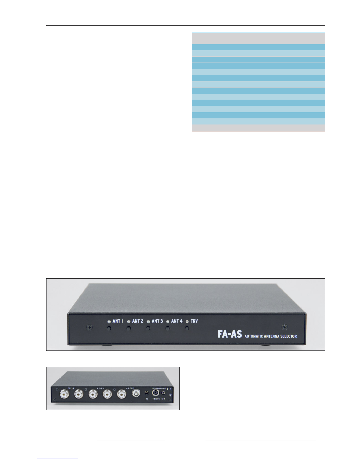
Table 1. Technical ata
Suitable controller Icom transceiver
Control information Line voltage or CIV command
HF connections up to four antennas and one transverter
Z = 50Ω, unbalanced
HF power ≤ 150W
Frequency range 0 … 72MHz*
Attenuation ≤ 0.1dB
SWR ≤ 1.2
Antenna memory EEPROM
Working voltage 12 … 15V
Current drain approx. 100mA@ 13.8V
imensions (W ×H ×) 238 ×33 ×240 mm3
Weight ≈ 1.8kg
* Automatic mode 1.8 … 72MHz
Picture 1a. Front view of the fully built FA -A
Tools and materials required for building:
– soldering iron 60W … 80W with pencil type fine point tip
along with 0.5 … 1mm. Resin core solder
– 100W soldering iron with flat tip
– side cutters for electronics
– flat nose pliers
– flat tip screwdriver
– small file
– spanner SW18 to mount the SO 239 sockets
– multimeter
– 50Ω dummy load (with temporary 100W capacity)
– bench power supply 10 … 15V@0.2A with adjustable
voltage and current thresholds
– C supply cable with 2.1 mm hollow round plug
(plug connector with kit parts)
Before mounting the board one should check and verify the
contents of the kit with the parts list provided. It contains in-
formation on the labelling of kit parts. Make sure to sort the
resistors to avoid accidental substitution during the build. If
sometimes the colour coding rings are not so easily identifi-
able then it is recommended to use an Ohmeter to check the
value, otherwise, poor performance due to an incorrect resis-
tor is subsequently not so easy to trace.
Picture 1b. Rear view of the fully built FA -A

Circuit
© www.funkamateur.de
4BX-7300 • 180403
4
Antenna 1
Antenna 2
Antenna 3
Antenna 4
Socket1
Socket 2
Socket 3
Socket 4
Socket 5
Socket 6
Socket 7
Socket 8
Socket 9
Line voltage
Hex code switch
Picture 2. Circuit diagram of the FA -A antenna selector

BX-7300 • 180403
© www.funkamateur.de 5
Automatic Antenna Selector
Hex code switch
Push button switches
Circuit
Central to the circuit is a microprocessor PIC
16F887 in a 40 pin IL housing. Its defined
firmware is essential to the operation of the de-
vice.
For the antenna and transceiver connections there
are five SO 239 sockets provided on the rear of
the FA-AS along with a BNC socket for the trans -
verter.
HF parts (delineated in picture 2 with a dotted
line) and control electronics are found on the same
board and isolated from each other by metal
screening.
In the case of non-selection, the respective outer
conductors make no circuit connection to the re-
maining sockets. This prevents adjustment prob-
lems that could occur where the coax cable of the
not selected antennas starts working as a random
additional counterpoise to the active antenna.
Were this considered unnecessary then the separat-
ing gap between the contact points on the socket
board could subsequently bridge over.
In the stand by state, the outer conductor of the
connected cables is short circuited with the match-
ing inner conductor. As long as the FA-AS is
switched off the transceiver associates with an-
tenna 1.
The SWR at the end of the connected antennas
feed line should be up to about 3, within a certain
range that otherwise the transceivers antenna tuner
can’t match, in any case, higher values on account
of extra co ax cable attenuation are unfavourable.
For the switching element there is the 12V power
relay K1 to K5. Controlled by IC2 this takes its
control commands over a serial interface with IC1.
As well, on the rear of the FA-AS there is a sepa-
rate C supply socket for a 2.1mm hollow round
plug (socket 7), a 3.5mm jack socket for the CI V
interface (socket 9) and a 6 pole mini IN socket
over which the PTT signal, line voltage and if ap-
plicable the transceiver supplied working voltage
are sent (socket 8).
Many Icom transceivers, including the IC 7300,
have a 13.8V supply on one pin of the ACC
socket, to power peripheral equipment. It is rated
1A at most and can be used to power the FA-AS
and in this case will be switched on and off to-
gether with the transceiver. Alternatively, the C
supply to socket 7 is possible noting that the FA-
AS has no independent on/off switch.
Operation of the FA-AS is carried out with the aid
of five push button switches S1 to S5. They lie di-
rectly on the microprocessor port pins and through
internal pull up resistance achieve a 5V potential.
LE 1 to LE 4 (bicolour red/green) and LE 5
(blue) indicate the working status. The line volt-
age fed from socket 8 passes across the voltage di-
vider on R7 and R10 to port RA0 of the PIC and
thus to the A/ converter.
The inverted PTT signal from VT 1 is fed to port
RB 5 and analysed in the case of separate transmit
and receive antenna operations. It may be running
both either high or low. With direct connection to
Icom transceivers it must be the latter. Then the
solder bridge J1 must be closed. Through the port
expander IC6 the controller reads the presented
hexadecimal code address from the coding
switches S6 and S7 via the I2C Bus. The driver IC
SN75451 (IC5) is associated with the CIV inter-
face and is connected to the EUSART module IC1
TX and RX ports.
The jumper contact points at J2 serve to install pa-
rameters and system requirements to the FA-AS.
The timing oscillator of the PIC works at
18.4320MHz. This peculiar frequency guarantees
that the internal frequency pitch Baudrate genera-
tor may produce exact values for the desired CI V
transformer rate. Centre connections on J2 are for
1200 Bd. or 9600 Bd. settings, the lower rate con-
ceded to older transceivers.
For safety, when the transceiver is not transmit-
ting, the relay contacts and their associated inputs
are naturally load free. After that the controller
comes in with an HF indicator. Manual switching
during transmit is blocked by the firmware. Line
voltage commands and data traffic over the CIV
interface are likewise non responsive.
The HF indicator is adjacent to the transceiver
input of the FA-AS and activates with some 5W of
power. IC4 on the HF side is separated from the
remaining circuit by a metal screen. Its output is
fed to port RA 1 of the processor whose A/ con-
verter evaluates the C voltage. The FA-AS re-
quires a supply voltage between 12V and 15V and
can use a regular station supply such as that of-
fered by the transceiver.
IC3 stabilises the working voltage from the supply
voltage to 5V. The current requirements of the ap-
paratus are a maximum of 100mA@13.8V. It is
attached to the relay switch circuit.

© www.funkamateur.de
Automatic Antenna Selector Mounting
6BX-7300 • 180403
Mounting the main board
If only for the sake of a well completed job, the circuit board
is supplied pre printed with the component layout. This
makes it a little easier to solder the additional pieces into
their correct positions, equally how those might be found in
the event of investigating a fault.
Attention: N.B. Regular constructors reading this
should bear in mind that if the board with the SO 239
sockets is finished and soldered to the main board then
it’s expedient to solder the relays first.
The mounting begins with the soldering of the surface com-
ponents in this case resistors R1 to R22. Using the multime-
ter set as Ohmeter these should be checked for safetys sake
so that no erroneous substitution can occur. Just a little note
here that the 4.7 KΩ metal film resistors R1 R2 and R7 may
be distinguished from the carbon film resistors by their blue
coloured base. R23 and R24 are left unmounted.
Then follow the chokes L1 to L7 they look a little fatter than
the resistors. ( on’t get confused and swap R18 … R21!)
After, the diodes V 1 to V 9 should be installed. V 1
and V 2 are 1Adiodes 1N4007, V 3 is a Schottky diode
and V 7 a 5.1VZ diode, or by any other name, a universal
1N4148 diode.
Next are the capacitors and both of the resistance networks
RN1 and RN2 in sequence. The correct installation orienta-
tion of the electrolytic capacitors should be adhered to. The
positive connection is clearly marked on the board and on
the component the negative side is usually marked, gener-
ally the side with the shorter wire.
N.B. on the written side of the resistance network cases
there is a printed spot, this marks pin 1 and is also labelled
on the board. Here great care must be taken that they are
correctly positioned as they are very difficult to remove.
Following on, the transistor VT1 (take note of the correct
orientation printed on the board), the IC socket for IC1, both
the haexadecimal encoders S6 and S7 and the push buttons
S1 to S5 can be soldered.
With the IC socket, the indentation should be in the direction
of the one marked on the board. This reduces the risk that
IC1 is later set incorrectly in the socket. The encoders have a
point on the casing upperside which after soldering must
match up with the corresponding mark on the board.
After soldering, the five push buttons must have their frame
edges sitting on the board. With the soldering, not too much
solder should flow through the holes towards the buttons so
as not to be the cause of a subsequent short circuit.
Now follows the fitting of the three input connectors socket
7 socket 8 and socket 9. Here too, their undersides need to
sit on the board.
Subsequently the fuse holder for the cut out fuse F1, the two
row connector strip J2 and the Quartz xtal Q1 should be sol-
dered in place. The last one should be mounted with an ap-
Picture 3. View of mounted parts in the area of antenna sockets 7
to 9.
Picture 4. Mounted components in the area of the DC supply and
relay control.
Picture 5. oldered coding switches and resistance networks

BX-7300 • 180403
© www.funkamateur.de 7
Mounting Automatic Antenna Selector
proximate 0.5mm spacing off the board so as to avoid an
eventual accidental short circuit caused by solder flows to-
wards the Quartz casing.
A short piece of wire is soldered adjacent to the casing. It is
to be noted that the Quartz housing is to be only briefly
heated and very quickly soldered with the 400 deg C. solder-
ing iron and only for as long as the solder flows. (If you're
not confident soldering this particular case then the piece of
wire can be left out as it only serves to additionally reduce
any spurious emission of the already well constrained
Quartz oscillator and has no special other function.
Pictures 3 to 7 show various stages of construction and can
be used to show orientation. For the first IC, mount the 5 V
voltage regulator IC3. This is shown mounted in picture 8.
First the three connectors must be bent with the aid of some
tweezers at about 4mm from the housing. These will be
fixed into the holes before laying the chip flat in the correct
position on the board. Under light pressure (to transfer heat
to the wider casing) warm the top end of the flat cooling
vane of IC3 with the help of a 100W soldering iron and
at the same time tip some solder into the inside of the
3.6mm hole in the cooling vane. After a short time the cas-
ing will be hot enough so that any solder remaining in the
crack under the IC runs away.
Picture 6. Mounted push buttons
Picture 7. Earthing wire on Quartz housing.
Picture 8. oldered 5 V voltage regulator

© www.funkamateur.de
Automatic Antenna Selector Mounting
8BX-7300 • 180403
Picture 9. ite of test point M and +5V.
Picture 10. Correct build positioning of IC 2; the site of the in-
dentation (arrowed) is to be paid attention to.
Picture 12. With IC 5 the marker point must be nearest the edge
of the board.
Picture 13. Position of IC 6 after mounting.
Picture 11. Optical coupling device IC4 soldered in position.
Testing the DC su ly
Using the kits accompanying hollow round plug and a twin
core cable, the C supply should be assembled. The sup-
plied fuse should be placed in its holder and the bench
power supply set to 12V with a current threshold of 0.2A.
The voltage output from the bench supply is now connected
via the C supply cable to socket 7. With the multimeter at
the +5V test point (picture 9) there should be a reading of
between 4.9V and 5.0V. If not, then it’s the old task of find-
ing out why and correcting the problem before mounting
any more components. As a reference point for calibration
for example, the test point M, near to the fuse, may be used.
When everything is in order the C supply and board may
be disconnected.

Mounting the IC’s
Now follows the mounting of IC2, IC4, IC5 and IC6. It is of
course, crucial they are mounted in the correct orientation.
The position of the indentation must correspond with the di-
agram on the circuit board. The soldered IC’s can be seen in
pictures 10 to 13.
Mounting the socket board
The approximately 1.5mm gap on the back edge of the main
board is so designed that the socket board can be inserted
later. The milled corners may however need a little further
rounding off with a small file and lastly, the socket plate
must sit flush in the main board gap as shown in picture 14.
With the dimensions of the SO239 sockets adhering to as
high a tolerance as possible it can be that a negligible
amount of filing is required afterwards. The aim is that when
the sockets are mounted and sitting in their corresponding
holes there is as little play as possible and that when the are
being screwed and unscrewed they don’t move or twist and
remain stable. In this case the flat side of the hole (shown in
picture 15) may be carefully and gradually worked so that
the fitted socket has no movement. (In practice only a few
file strokes are needed).
Now the five SO239 sockets are set in a row on the socket
board with the copper side and solder tags facing the same
direction, the nuts located and turned hand tight. Then the
socket board may be screwed to the rear panel using three
black countersunk cabinet screws and M3 ×6 nuts. The
sockets must be aligned as much as possible central to the
rear panel holes and not touching (as shown in picture 16).
With the aid of an appropriate spanner the nuts on the cop-
per coated side of the board are tightened. After which the
rear panel together with the socket board are joined together
with the main board using two metal blocks and two M3 ×4
housing screws and two M3 ×4 cylinder screws. The socket
board is now in the position it will take in the finished hous-
ing and can be mechanically fixed and electrically con-
nected.
There now comes to pass the joining together of the solder
connections of the sockets and main board by the use of a
100W soldering iron and sufficient solder for both sides to
be soldered both from the top of the board and from the un-
derside. This part is shown in a section of the top side of the
main board in picture 17.
When soldering in the corner of the main board it is easier to
have it inclined by 45 deg. Also to bear in mind is that the
insulated leg at any one time is not accidentally bridged to
the adjacent socket section. The legs are quite wide with a
limited tolerance, make sure to check the alignment.
Mounting Automatic Antenna Selector
BX-7300 • 180403
© www.funkamateur.de 9
Picture 14. The socket board after a little filing, must fit exactly
in the gap of the main board.
Picture 15. If necessary only the flat edges of the through holes
should be carefully worked.
Picture 16. The five O 239 sockets should be mounted such that
they are centred in the holes on the rear panel.
Picture 17. hown here a section of soldered main board and
sockets in a row.

© www.funkamateur.de
Automatic Antenna Selector Mounting
10 BX-7300 • 180403
After this the housing rear panel should be unscrewed so
that during the next stage it won’t be accidentally scratched.
The connections between the solder points of the central
conductors of the sockets and the main board are made with
short pieces of 1mm diameter silvered copper wire (picture
18).
Building the relay and LED’s
After the socket board is completely mounted the BNC
socket and the five relays are soldered, they should lay flat
on the board.
Then next is to prepare the five LE ’s for mounting. The
advice in this case, so they aren’t accidentally mixed up, is
that the blue one (LE 5) which has a clear glass should be
separated from the bicolour LE ’s whose plastic bodies ap-
pears slightly opaque. Cut ten pieces of wire insulation of
22mm length and push onto the LE connection wires.
These must be bent 90 deg. att 12mm from the LE body
and will appear as shown in picture 19. Subsequently when
viewing the LE ’s from the front you must make sure that
the longer of the two wires is located to the left. From the
length of the insulator material the installation height off the
main board is a given and should be around 10mm.
The front panel serves as a template for adjusting the LE ’s
before soldering the connections. Now take two of the metal
cube joining blocks and attach them to the board with
M3×4 screws as shown in picture 20. Then take the LE ’s
and their connectors and fit them to their respective holes
(LE 5 is the light diode with the clear glass housing).
Afterwards loosely screw the front panel to the metal blocks
with two black housing screws, now the LE ’s can be
evened up parallel and best positioned in their respective
holes (picture 21). Now the LE ’s can be soldered and the
front panel unscrewed again.
Picture 21. Fully aligned LED’s, with help from the front panel.
Picture 19. Prepared LED for building.
Picture 20. Position of the two metal blocks for attaching the
front panel.
Picture 18. The solder tag of the inner conductor of each socket is
joined to the main board with the help of a piece of silvered wire.
Table des matières


