Fullriver Battery DC Series Manuel utilisateur

INSTALLATION AND
OPERATION MANUAL

FULLRIVER BATTERY
3823 Mission oaks Blvd, ste a
CaMarillo, Ca 93012
This publication is protected by copyright. All
rights are reserved. At no point, may any part
of this publication be copied, reproduced, or
transmitted by any means or any format without
prior written consent from Fullriver Battery.
Fullriver Battery is not liable for direct, indirect,
special, exemplary, incidental or consequential
damages that may result from any information
provided in or omitted from this manual, under
any circumstances.
Fullriver Battery reserves the right to make
adjustments to this manual at any time, without
prior notice or obligation.
Fullriver Battery and the Fullriver Battery logo are
registered trademarks of Fullriver Battery Mfg.
Co. Ltd.
CONGRATULATIONS ON YOUR
PURCHASE OF A FULLRIVER BATTERY!
Maximize the performance of your new battery
by thoroughly reading this manual.

Table of Contents
1. GETTING STARTED..............................................2
1.1 - Safety
1.2 - Equipment checklist
2. INSTALLATION ............................................... 3-7
2.1 - Selecting the appropriate cable size
2.2 - Terminal connections
2.3 - Battery orientation
2.4 - Series connections
2.5 - Parallel connections
2.6 - Series / parallel connections
2.7 - Cross tying batteries in parallel packs
2.8 - Charging batteries before use
3. OPERATION ................................................. 8-9
3.1-Temperatureeectsonbatteryperformanceandlife
3.2 - Operating temperature range
3.3-Lowdischargerateeects
3.4 - Depth of Discharge (D.O.D.) vs. Battery Life
4. CHARGING ................................................10-11
4.1 - Charger inspection
4.2 - Charging your Fullriver batteries
4.3 - Charging temperature range
4.4 - Charging parameters
4.4.1 - Current
4.4.2 - Voltage settings
4.4.3 - Temperature compensation
5. STORAGE..................................................12-13
5.1-Batterystorageprocedure
5.2-Temperatureeectsonself-discharge
5.3 - Storage temperature range
6. TESTING ..................................................14-16
6.1 - Test preparation
6.2 - Open circuit voltage test
6.3 - Discharge test
6.4 - Optional test
6.5 - CCA test
6.6 - Battery replacement instructions
7. YOUR CLEAN-GREEN ENERGY SOLUTION ......................16-17
7.1-Fullriverproducts
7.2 - Fullriver manufacturing
7.3-Solarsettingrecommendations
8. TRANSPORTATION INFORMATION...............................18
A. APPENDIX ....................................................19
A.1 - Temperature ranges
A.2 - State of Charge (S.O.C.) vs. Open Circuit Voltage (O.C.V.)
A.3-Bolt/NutSpecications

Page d
Notes
INSTALLATION AND
OPERATION MANUAL

Page 1
INSTALLATION AND
OPERATION MANUAL

Page 2
BeforeinstallingyourFullriverbattery,pleaseadheretothefollowingsafety
guidelinesandmakesurethatyouhavetheproperequipmentforinstallation,
operation,anddiagnostictesting.
1.1 - SAFETY
PROTECT YOURSELF AND PROTECT YOUR BATTERY
•Wearprotectivegear,includinggloves,whenhandlingabattery.
•Installandremoveabatteryusingtheliftinghandlesprovided.
•Useawrenchwitharubbercoatedhandleforinstalling,tightening,or
removing battery connections.
• Do not place any objects on top of a battery.
• Do not smoke near a battery.
•Keepames,sparksandmetalobjectsawayfromabattery.
•Chargebatteriesinaventilatedarea-althoughAGMandGelbatteries
typicallydonotreleasegas.Thesafetyvalvemayopentoalleviateexcess
pressureifthebatteryisover-charged.
ALWAYS USE CAUTION AROUND A BATTERY
1.2 - EQUIPMENT CHECKLIST
Gloves
Wrenchwithinsulated/rubbercoatedhandle
Voltmeter
Charger
Discharger (if available)
Getting Started

Page 3
Properbatteryinstallationistherststepingettingthebestperformanceoutof
your Fullriver battery.
2.1 - SELECTING THE APPROPRIATE CABLE SIZE
Cablesmustbesizedtocarrythemaximumexpectedload.Under-sizedcablescan
resultinover-heating,meltedconnectionsandareapotentialrehazard.
Refer to TABLE 1 below for the current carrying capacity by cable size. These values
are for cable lengths of 6 feet (1.83 meters) or less. It is preferable that all cables in a
series connection or in a parallel connection are the same length.
Tosignicantlyreducetheamountofheatgeneratedattheterminals,
usecableswithsolder-dippedends.
Installation
25
30
40
55
75
95
130
150
170
265
360
Ampacity (Amps)
14
12
10
8
6
4
2
1
1/0
2/0
3/0
Cable Gauge (AWG)
TABLE 1

Page 4
2.2 - TERMINAL CONNECTIONS
Terminalconnectionsmustbetightenedusingthecorrecttorquevaluesasdened
in TABLE 2below.Overorundertightenedconnectionscanresultinterminal
breakage,over-heatingand/ormeltdown.Usingthepropertorquevaluewillprovide
optimumconductivity.Toavoidashortcircuit,useawrenchwithaninsulatedor
rubbercoatedhandlewhenmakingterminalconnections.SeeDIAGRAM 1 below
for proper washer placement.
NEVER place a washer between the mating surfaces of the terminals
andcables.Thiswillcompromiseelectricaltransmissionandincrease
resistance,resultinginextremeheatgenerationandprobableterminal
melting.
Loctite®Threadlockermaybeusedtobettersecuretheterminal
connections. Be careful not to get Loctite®between the mating surfaces
of the terminal.
Installation
DIAGRAM 1
Terminal Type ft-lbs lbs-in Nm Terminal Type ft-lbs lbs-in Nm
M6, AP 4.1-5.8 50-70 5.6-7.9 M10M (Stud) 7.7-9.6 92-115 10.4-13
M8 7.1-7.9 85-95 9.6-10.7 3/8” Stud 8.9-12 106-150 12-16.9
M10 9.6-12 115-141 13-16 FR45 5.8-7.4 70-90 7.9-10.1
M6M (Stud) 3.3-4.6 40-56 4.5-6.3 TP06 (AP) 3.3-4.6 40-56 4.5-6.3
M8M (Stud) 4.9-6.3 58-75 6.6-8.5 TP08/TP68 (AP) 5.2-6.9 63-83 7.1-9.4
TERMINAL TORQUE SPECS

Page 5
2.3 - BATTERY ORIENTATION
Theidealplacementofbatteriesisupright.AGMandGelbatteriescanbeplacedon
theirsideifnecessary.Itispreferredthatallthebatterieswithinapackbeplacedin
the same orientation.
NEVERplacebatteriesinaninvertedorientation(terminalspointed
towardsground).
2.4 - SERIES CONNECTIONS
Thereismorethanoneoptiontomeetyourvoltagerequirements.Forexample,for
a12voltsystem,youmayuseone(1)12voltbatteryortwo(2)6voltbatterieswired
inaseriestomakeupthe12volts.Youmayuseasmanybatteriesasyouneedto
make up the system voltage. Connect the positive of one battery to the negative
ofthenextthroughtheentirestring.SeeDIAGRAM 2 below for the proper series
connection.
Installation
Series Connection:
Voltage is increased in a series connection
Two 6V, 224AH batteries = 12V, 224AH
DIAGRAM 2
Page 6
2.5 - PARALLEL CONNECTIONS
Thereismorethanoneoptiontomeetyourenergyrequirements.Forexample,to
meet the requirements for a 210 Amp-Hour system, you may use one (1) 210
Amp-Hourbatteryortwo(2)105Amp-Hourbatterieswiredinparalleltomakeup
the210Amp-Hours.Connectallthepositiveterminalstogetherandallthenegative
terminals together in the string. See DIAGRAM 3 below for proper parallel
connection.
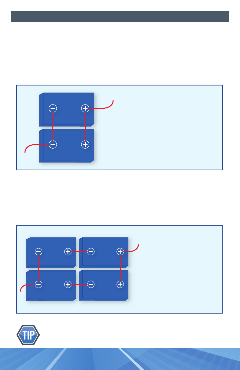
2.6 - SERIES / PARALLEL CONNECTIONS
Batteriescanbeconnectedinbothseriesandparalleltoattainthedesiredsystem
voltageandenergyrequirements.SeeDIAGRAM 4 below for proper series / parallel
connections.
Foroptimumperformance,thesystemspositiveandnegativeleads
shouldbeconnecteddiagonallyopposite(catty-corner)fromeachother.
Installation
Parallel Connection:
Capacity is increased in a parallel connection
Two 12V, 105AH batteries = 12V, 210AH
DIAGRAM 3
Series/Parallel Connection:
Voltage and capacity are increased in a
series/parallel connection
Four 12V, 115AH batteries = 24V, 230AH
DIAGRAM 4
Ce manuel convient aux modèles suivants
4
Table des matières


