FujiClean CE6KG Manuel utilisateur

Contractor Installation Manual
Commercial Systems
Including
H-20 Installation
CE and CEN Models
(except Model CE6KG)
Rev. 11-2 -20
Fuji Clean USA ● 41-2 Greenwoo Roa ● Brunswick Maine 04011 ● Tel: 207-406-2927 ● Fax: 888-789-1977 ● www.fujicleanusa.com
Warranty Activation. To activate system warranty, Fuji Clean USA must receive Warranty Activation Card!

Equipment Supplied to Contractor
Signalmaster Float
Switch
(Affix to pumpback line in center
chamber with 3-1/2” tether)
FujiMAC UL Approved
Air Blower(s) (Blower size and
quantity according to model. Blower
barb hole for smaller models
Alarm / Control Panel
(NEMA X Rated)
Thank you for choosing to install a Fuji Clean treatment system. We care that the system is
installed properly and thoughtfully. Fuji Clean USA or your qualified distributor will train and
certify you for proper installation. Please be aware that not every item below comes with every
model. Component needs vary according to model. Please call Fuji Clean USA with questions.
NSF Dataplates (2)
(Smaller models only)
Installation Manual, User’s Manual, Warranty Card
Fuji Clean Processor Tank
Air Vent Hole and Plug
(Tighten clockwise. Plugs the vent hole if
venting through building. Note: some
models have two vent holes.)
Risers & Covers (height may
vary – check with local distributor)
Blower adaptor Fitting
with Barb (For larger models.
Not provided/necessary with “M”
Alarm Panel)
1/8” (ID) Vinyl Micro-Tubing for Air
Pressure Sensing Alarm. (Not provided/necessary
with “M” Alarm Panel)
Eccentric Inlet/Outlet 5x Bushing (2) (Larger models
only)
2
Airline to Tank Adapter
(For CE1 and CEN10.
Unglued. Glue during installation.)

Equipment Supplied by Contractor
Risers an Access covers per Site & Regulatory Requirements
Risers in 6” or 12” height increments and access covers are available from your distributor. If not already installed,
please refer to installation instructions in this Manual. Maximum riser height is 2 inches for No traffic load and H-
20, HS-20 with Support Columns. For H-20, HS-20 with No Support Columns, acceptable riser height is 12 inches to
set the depth 2 inches between ground level and adapter ring.
All Commercial Mo els: Two (2) 20-inch dia. Risers plus One (1) 2 -inch dia. Riser.
Insulation for Col Climate Installations
To maintain optimal treatment conditions, Fuji Clean recommends insulated risers and access covers as well as
foam board or insulating material (min. R-Value 8) over the upper half of the treatment tank. In H-20, HS-20 with
No Support Columns installation, insulate at depth of 2 inches between ground level and adapter ring.
Septic Tank an /or Pump Station.
For commercial system, structure use with high influent load cases, install a septic tank if necessary. Fuji Clean
systems are designed to accept straight wastewater. However, some treatment train designs call for pretreatment,
settling and/or trash tanks.
Fresh Water
Systems must be filled with fresh water to Low Water Level before backfill. Please refer to Approx. gallons required
per model is “Volume Total” on page 7.
Piping / Con uit
•Smaller models have inlet/outlet adapters for sched. 0 ” pipe. Models CE1 , CE21, CE30, CEN1 , CEN21
fittings are for 5” sched. 0 pipe and come with a 5”: ” eccentric adaptors, to accommodate sched. 0 ” pipe.
•¾” or 1” PVC conduit for air line. Flexible irrigation line, 100 PSI Max, (or equivalent) is also acceptable.
•Electrical conduit for float switch line (direct burial line is also acceptable if allowed by code).
Electrical
•Please use licensed electrician and adhere to applicable national/local electrical code(s).
•Two (2) standard 115V, 15A circuits for control/alarm panel connection.
•Float Switch Wire: #18 AWG, comes with standard 30’ length. (Longer lengths are available on request).
•Float Switch: May come pre-installed in treatment system. For electrical hookup, please refer to SJE Rhombus
installation instructions.
•Miscellaneous fittings and connectors to assure watertight connections.
Anti-Float Devices, if necessary
•Please refer to high water, uplift restraint recommendations in this Manual.
Materials for Air Blower / Controller Installation
•Concrete base (or equivalent) on which to set air blower.
•Protective cover for air blower (recommended) vented and able to achieve free air flow in all conditions.
•Materials or location on which to mount control panel and protect from elements.
Crushe Stone, Fill, Loam etc.
•H-20 and HS-20 load needs concrete base.
•Fuji Clean USA is not responsible for design, installation or materials associated with leach field or treated
wastewater disposal area.
Please note: Proper installation permitting is the responsibility of the installing contractor.
Contractor Installation Manual – Commercial Systems
3
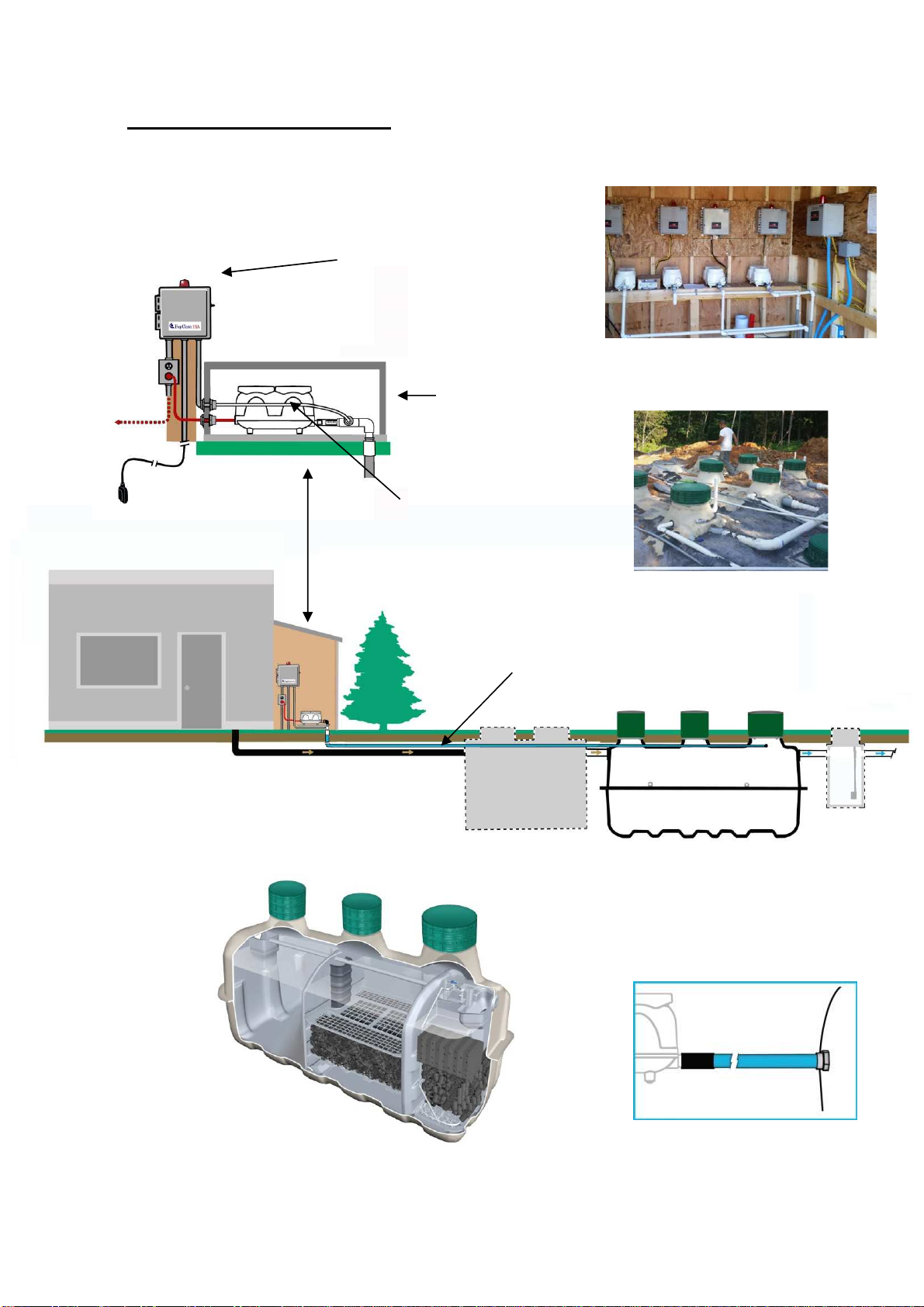
Installation Overview
Fuji Clean USA
Treatment System
Please Note: Fuji Clean systems are designed to accept straight
wastewater. However, some treatment train designs call for
pretreatment, settling and/or trash tanks.
Sched. 0 PVC inlet and outlet pipe
Air line to Treatment System
Pump Station
(if site conditions
dictate)
Septic Tank
(Optional)
MAC “R” Air
Blower
Adaptor and fittings (supplied by Fuji Clean
USA) for connection between treatment
system and FujiMAC Series “RII” Air blower.
System Controller/Alarm
including options for
telecommunication, simplex
and duplex pump control,
flow monitoring and data
logging.
FujiMAC “RII”
Commercial Series
linear diaphragm air
blower, typically 150-
300 liters/min for
commercial
applications.
Systems may be clustered
in parallel configuration for
treatment of larger flows.
Fuji Clean commercial
treatment systems are
delivered plug & play ready
with no onsite assembly
required.
Multiple system configurations may be
controlled independently (shown) or by
one customized controller.
Air pressure line is not supplied
with systems that use an “M”
panel as current sensors are
used instead.

Treatment Process Overview
Fuji Clean’s “contact filtration” treatment is a simple, well engineered process that consists of a controlled, circuitous
flow train through anaerobic and aerobic chambers and in direct contact with assorted proprietary fixed film medias
on which biological digestion of organic matter occurs. Media is also designed and positioned to provide mechanical
filtration of process wastewater.
The system includes two air lift pumps (see diagram below). The Recirculating Airlift Pump returns process water and
sludge from the aerobic zone to the sedimentation chamber, recirculating 2- times inflow per day for CE models and
-6 times inflow for CEN (enhanced denitrification) models. The Effluent Airlift Pump is designed to help equalize flow
and discharge treated effluent.
5
Outlet
Air
Slu ge Transfer
(Recirculating air lift pumpback)
Chamber 3B. Disinfection Chamber
(final zone before discharge – option for chlorination tablet disinfection)
Chamber 1.
Se imentation Chamber
(separates solids and greases)
Chamber 3. Aerobic Contact
Filtration Chamber
(both board and cylindrical hollow
mesh media) oxygen rich zone for
aerobic microbe digestion activity,
solids filtration and nitrification of
ammoniac nitrogens to nitrates
Powere by the FujiMAC “Rll” Series
Blowers State-of-the-art linear
diaphragm air blowers manufactured
by Fuji Clean Co sized to provide
about 2.8 cubic feet per minute to
most Commercial systems.
Chamber 2.
Anaerobic Filtration Chamber
(spherical-skeleton filter media)
organic matter decomposition by
micro-organisms, suspended
solids are captured and nitrates
are denitrified
Chamber 3A. Clarification Chamber (settling zone)
Two Air Lift Pumps. One Recirculating Air
Lift pump sending process water and solids
back to Chamber 1, and one Effluent Air Lift
Pump for measured discharge of treated
effluent. (See airlift pump info below).
Airlift Pumps. This generic illustration
shows the mechanics of the “airlift
pumps” used in this system, which are
simple pipe conduits through which
pressurized air (from blower) is
introduced at the bottom and by fluid
pressure, water is carried up the pipe
by ascending bubbles.
Flow Equalization
When water level
exceeds LWL, treated
water is discharged
through Chamber 3B
via the Effluent Air Lift
pump. If water level
exceeds HWL, then
treated water is also
discharged through an
overflow effluent weir.
Overflow Effluent Weir
During treatment,
water level fluctuates
between high and
low water levels
Inlet

6
System Components an Specifications - Summary
* TN data was obtained during CE testing, but not to NSF2 5 testing protocol. CEN testing was to NSF2 5 protocol.
** Please consult with distributor or Fuji Clean USA for commercial models designed to treat hydraulic flows above
those listed in this table.
*** Please consult with distributor or Fuji Clean USA for system specification and sizing in cases where influent
biologic strength is greater than domestic strength.
Structural drawings of all Commercial models are available in both .dwg and pdf formats online
at www.fujicleanusa.com
7
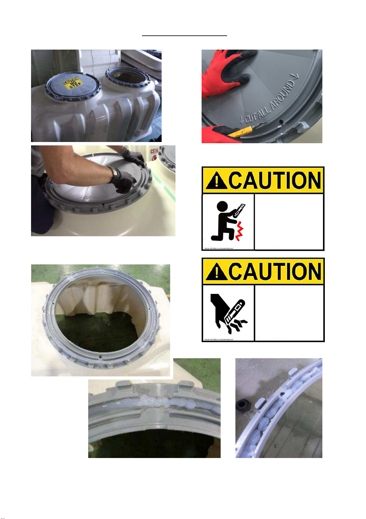
Use sharp bla e to remove inner plastic ring.
*Safety consi erations!
Squeeze silicone
or approve
waterproof
sealant into base
frame groove.
20-inch ia.
(1st an 2n Openings)
24-inch ia.
(3r Opening)
Riser Installation-1
INJURE YOUR
LEGS WHEN
YOUR HAND
SLIPPED
CUT YOUR
FINGERS WHEN
YOUR HAND
SLIPPED WITHOUT
GLOVES
Sli e several times on the cutting groove
is easier.

8
Polylok Risers. Align mol e “frame block” with riser screw hole. Insert screw an screw tight.
Recommen e screw length: 1 ½” (If it's too long, it won't fit in "frame block“.)
Riser Installation-2
Tuf-Tite Risers. Align riser screw holes with mol e “frame block”
an screw tight.
Recommen e screw length: 1 ½”
(If it's too long, it won't fit in "frame block“.)
frame
block
Apply silicone to
the screw hea
to prevent water
penetration.
MAKE SURE TO INSTALL RISER ON PP-ADAPTER RING.

No-traffic Area Installation Procedure
Step 1: Prepare excavation to be at least 1 to 2 feet
larger than Fuji Clean system imensions as liste in the
Design Specification Table on page 7 of this Manual.
Important Note: Total height from tank top to gra e
shoul not excee 24”.
Step 2. Prepare 4”- 6” be of stone (1/8”), compact
san , poure or precast concrete level to within 1/8”
per 2 feet. (10mm per 2 meter or 1/200).
Unloa ing Instructions:
Upon delivery, inspect Fuji clean tank, both outside and inside for possible damage incurred
during transport. If you find damage, or have a question, please contact your distributor
immediately.
9
Compact stone or san
Use ALL 4-point lifting lugs
Step 3: Carefully lower an set tank.
Level to within 1/8” per 2 feet.
(10mm per 2 meter or 1/200).

10
Step 4: If any part of the tank is below the estimate seasonal high water table, then engineer shall
provi e buoyancy calculations to assure a equate tank uplift restraint.
CONCRETE UPLIFT RESTRAINT REQ’D FOR FUJI CLEAM CE,CEN SERIES MODELS BASED ON GROSS TANK DIMENSIONS
MODEL HEIGHT
(FT)
WIDTH
(FT)
LENGTH
(FT)
VOLUME
(FT3)
DISOLACEMENT
(LBS)
CONCRETE VOLUME (CY)
@3050
LB/CY
WITH
10% FS
WITH
25% FS
WITH
50% FS
CE1 /CEN10 6. 167 5.750 9.9167 366 22,839 7. 9 8.2 9.36 11.23
CE21/CEN1 6.8750 6.000 12.7292 526 32,823 10.76 11.8 13. 5 16.1
CE30/CEN21 7.3333 6. 792 16.250 773 8,236 15.82 17. 0 19.77 23.72
SLAB DIMENSIONS FOR 50% FACTOR OF SAFETY
MODEL CONCRETE VOLUME (CY)
WITH 50% FS
SLAB WIDTH
(FT)
SLAB LENGTH
(FT)
SLAB THICKNESS
(FT)
CE1 /CEN10 11.23 6.00 10.00 5.055
CE21/CEN1 16.1 6.00 13.00 5.588
CE30/CEN21 23.72 7.00 17.00 5.382
Tie own straps
Do NOT use Lifting Lugs
for uplift restraint.
TIE-DOWN
STRAPS
Table des matières
Autres manuels FujiClean Système d'eau


Manuels Système d'eau populaires d'autres marques

Spirotech
Spirotech SPIROVENT SUPERIOR S250 Manuel utilisateur

Culligan
Culligan Aqua-Cleer Aqua-Cleer Advanced Drinking Water... Manuel utilisateur

A.O. Smith
A.O. Smith Dura-Max AJH - 1000A - P Manuel utilisateur

Microline
Microline T.F.C.-4 Manuel

Eureka Forbes
Eureka Forbes Aquaguard Select Manuel utilisateur

Cetetherm
Cetetherm AquaEfficiency Manuel utilisateur


