Froling Lambdatronic S 3200 Manuel utilisateur

Operating Instructions
Boiler controller Lambdatronic S 3200 - Touch
Version 50.04 - Build 05.09 | Version 60.01 - Build 01.23
Translation of the original German operating instructions for technicians and operators
Read and follow the instructions and safety information!
Technical changes, typographical errors and omissions reserved!
B0840314_en | Edition 21/07/2014
Froling GesmbH | A-4710 Grieskirchen, Industriestraße 12 | www.froeling.com

Table of Contents
1 General 5
1.1 About these instructions 5
1.2 Safety information 5
2 Electrical connection and wiring 6
2.1 Core module and connection options 6
2.1.1 Board view 6
Connection instructions
7
2.1.2 Mains connection 8
2.1.3 Connecting the flue gas sensor 8
2.1.4 Combination with oil burner 9
2.1.5 Valve for flue gas condenser connection 9
2.1.6 Connecting the remote control 10
2.1.7 Connecting a high efficiency pump to the core module 11
2.2 Expansion modules 12
2.2.1 Heating circuit module 12
2.2.2 Hydraulic module 13
Connecting an isolating valve
14
Connecting a high efficiency pump to the hydraulic module
15
2.2.3 Return mixer module 16
2.2.4 Ignition expansion 18
2.2.5 Connecting the bus cable 18
2.2.6 Connect the patch cable to the bus plug 19
2.2.7 Setting end jumpers 19
2.2.8 Setting the module address 20
2.3 Connection diagrams according to pump types 20
3 Overview of the basic functions 22
3.1 Visual display 22
3.1.1 Status LED 22
3.1.2 Control icons 23
3.1.3 Display icons 24
3.2 Operating statuses 25
3.3 Updating the software of the touch control 26
3.4 Calibrating the touchscreen 28
4 Operation 30
4.1 Before switching on for the first time 30
4.1.1 Controller check 30
4.1.2 Check on the connected units 30
4.1.3 System Check 30
4.2 Navigation within the info menu 31
4.3 Navigation within the system menu 31
4.3.1 Navigating the menus 32
4.4 Adjusting parameters 34
4.5 Setting times 35
4.6 Setting the date/time 37
Table of Contents
2 Froling GesmbH | A-4710 Grieskirchen, Industriestraße 12 | www.froeling.com

4.7 Quick menu 38
4.7.1 "Operating level” function 38
4.7.2 "Choose language” function 38
4.7.3 "Chimney sweep” function 38
4.7.4 "Extra heating” function 38
4.7.5 “Mode in automatic mode” function 38
4.7.6 "Extra loading” function 38
4.7.7 “Ignition” function 38
4.7.8 "Touch cleaning” function 38
4.8 Initial startup 39
4.8.1 Switching user level 39
4.8.2 Setting the system selection 40
Open the system selection menu
40
Selecting the boiler type
41
System selection
43
DHW tank system
44
Heating system
45
Solar system
45
Boiler remote control
46
4.8.3 Before heating up for the first time 46
Drives
46
5 Menu overview and parameters 47
5.1 Menu - Heating 47
5.1.1 Status displays for the heating circuits 48
5.1.2 Temperature settings for the heating circuits 49
5.1.3 Heating times of the heating circuits 50
5.1.4 Service parameters of the heating circuits 50
5.1.5 Service parameters for heating up program 51
Heating up programs
53
5.1.6 General Settings 54
5.2 Menu - Water 54
5.2.1 Status displays for the DHW tank 55
5.2.2 Temperature settings of the DHW tank 55
5.2.3 Heating times of the DHW tank 56
5.2.4 Service parameters of the DHW tank 56
5.3 Menu - Solar 57
5.3.1 Status displays for the solar system 58
5.3.2 Temperature settings for the solar system 59
5.3.3 Service parameters of the solar system 60
5.3.4 Solar heat meter 62
5.4 Menu - Storage tank 63
5.4.1 Status displays of the storage tank 64
5.4.2 Temperature settings for the storage tank 64
5.4.3 Service parameters of the storage tank 65
5.5 Menu - Boiler 66
5.5.1 Status displays for the boiler 67
5.5.2 Temperature settings for the boiler 67
5.5.3 Service parameters of the boiler 68
5.5.4 General Settings 68
Operator data
69
5.6 Menu - Boiler 2 69
5.6.1 Status displays for the backup boiler 70
5.6.2 Temperature settings for the backup boiler 70
Table of Contents
Operating Instructions Lambdatronic S 3200 - Touch | B0840314_en 3

5.6.3 Service parameters of the backup boiler 71
5.7 Menu - Ignition 72
5.8 Menu - Network pump 74
5.8.1 Network pump status displays 75
5.8.2 Network pump temperature settings 75
5.8.3 Service parameters for the network pump 76
5.9 Menu - Difference regulator 77
5.9.1 Status displays for the difference regulator 78
5.9.2 Temperature settings for the difference regulator 78
5.9.3 Service parameters for the difference regulator 79
5.10 Menu - Circulation pump 79
5.10.1 Status displays for the circulation pump 80
5.10.2 Temperature settings for the circulation pump 80
5.10.3 Time settings for the circulation pump 81
5.10.4 Service parameters of the circulation pump 81
5.11 Menu - Manual 82
5.11.1 Digital outputs 83
5.11.2 Analogue outputs 83
5.11.3 Digital inputs 84
5.12 Menu - System 84
5.12.1 Setting 85
Adjustable parameters: Boiler temperature
85
Adjustable Parameters: Flue Gas
86
Adjustable parameters - Ignition
87
Adjustable Parameters: Air settings
88
Adjustable parameters: Lambda values
89
Adjustable parameters: Lambda values - LSM11 Lambda probe
89
Adjustable parameters: Lambda values – Broadband probe
90
Adjustable parameters: General settings
92
5.12.2 Current values 93
5.12.3 Sensors and pumps 94
5.12.4 Display operating rights 95
Froeling Connect
96
5.12.5 Display allocation 96
5.12.6 System selection 97
5.13 Menu - Diagnostics 97
5.13.1 Error display 98
5.13.2 Error history 98
5.13.3 Clear error history 99
5.14 Menu - Display settings 99
5.14.1 General 100
Network settings
101
5.14.2 Date / Time 101
5.14.3 Software update / Service 102
5.15 PWM / 0 - 10V settings 102
6 Troubleshooting 104
6.1 Procedure for fault messages 104
7 Setting protocol 106
Table of Contents
4 Froling GesmbH | A-4710 Grieskirchen, Industriestraße 12 | www.froeling.com

1 General
1.1 About these instructions
Please read and follow the operating instructions, in particular the safety information
contained therein. Keep them available next to the boiler.
These operating instructions contain important information about operation, electrical
connection and troubleshooting for the Lambdatronic S 3200 control.
NOTICE
The values given in the parameter lists are examples, and
should not be used as standard values!
The constant further development of our products means that there may be minor dif‐
ferences from the pictures and content. If you discover any errors, please let us know.
1.2 Safety information
DANGER
When working on electrical components:
Risk of electrocution!
When work is carried out on electrical components:
❒ Only have work carried out by a qualified electrician
❒ Observe the applicable standards and regulations
➥Work must not be carried out on electrical components by unauthorised
people
WARNING
When touching hot surfaces:
Severe burns are possible on hot surfaces and the flue gas pipe!
When work is carried out on the boiler:
❒ Shut down the boiler in a controlled way (operating status "Off") and allow it to
cool down
❒ Protective gloves must generally be worn for work on the boiler, and it should
only be operated using the handles provided
❒ Insulate the flue pipes or simply avoid touching them during operation.
The information on safety, standards and guidelines in assembly and operating in‐
structions for the boiler should also be observed.
General 1
About these instructions
Operating Instructions Lambdatronic S 3200 - Touch | B0840314_en 5
2 Electrical connection and wiring
2.1 Core module and connection options
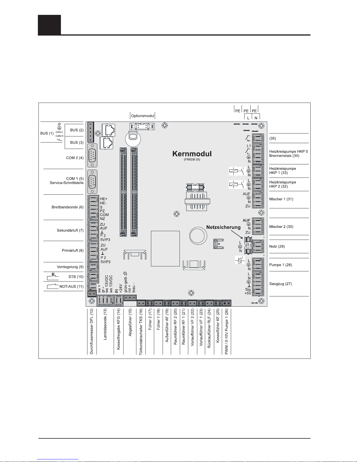
2.1.1 Board view
2Electrical connection and wiring
Core module and connection options
6 Froling GesmbH | A-4710 Grieskirchen, Industriestraße 12 | www.froeling.com

Connection instructions
Port Cable dimensions / Specifications / Information
Bus (1) Port with cable – LIYCY paired 2x2x0.5;
⇨ See "Connecting the bus cable" [page 18]
❒ Warning! CAN L and CAN H must not be connected to +UBUS!
Bus (2) Patch cable CAT 5 RJ45 SFTP 1:1 configuration
Bus (3) Patch cable CAT 5 RJ45 SFTP 1:1 configuration, boiler display port
COM 2 (4) Null modem cable 9-pin SUB-D;
❒Port can be used as a MODBUS interface
General Settings
COM 1 (5) Null modem cable 9-pin SUB-D;
❒Service interface for installing new boiler software or port for the visualisation
software
Broadband probe (6) Connection cable1) 5 x 0.75 mm2
❒Connection of a BOSCH or NTK broadband Lambda probe
Secondary air (7) Connection cable1) 5 x 0.75 mm²
❒When using the S1 Turbo firewood boiler, the air flap must be connected a the
“Secondary air” connection port
Primary air (8) Connection cable1) 5 x 0.75 mm²
Latch (9) Connection cable1) 2 x 0.75 mm2
High-limit thermostat - STL (10)
EMERGENCY STOP (11) Connection cable1) 2 x 0.75 mm2
❒Warning! Do not connect the emergency off/emergency stop switch to the power
supply cable of the boiler. The switch must be a N/C switch and it must be linked
to the 24V safety chain of the STL at this terminal.
Flowmeter FLM (12) Connection cable1) 2 x 0.75 mm2
Lambda probe (13) Connection cable1) 4 x 0.75 mm²
❒LSM11 Lambda probe connection
Boiler release (14) Connection cable1) 2 x 0.75 mm2
❒Warning! The connection must be a floating connection.
Flue gas temperature sensor (15) Connection cable1) 3 x 0.75 mm2
Door switch DCS (16) Connection cable1) 2 x 0.75 mm2
Sensor 2/1 (17/18) Connection cable1) 2 x 0.75 mm2
Outside temperature sensor (19) Connection cable1) 2 x 0.75 mm2,shielded from 25m cable length
Room temperature sensor 2/1
(20/21)
Flow temperature sensor 2/1
(22/23)
Return sensor RTS (24) Connection cable1) 2 x 0.75 mm2
Boiler sensor BS (25)
PDM / 0-10V Pump 1 (26)
Induced draught (27) Connection cable1) 3 x 1.5 mm2, power supply
Connection cable1) 3 x 0.75 mm2, analysis of current speed
Electrical connection and wiring 2
Core module and connection options
Operating Instructions Lambdatronic S 3200 - Touch | B0840314_en 7

Port Cable dimensions / Specifications / Information
Pump 1 on core module (28) Connection cable1) 3 x 1.5 mm2, max. 1.5A / 280W / 230V
Mains (29) Connection cable 1) 3 x 1.5 mm2; fused with 16A (provided by the customer)
Mixing valve 2/1 (30/31) Connection cable1) 4 x 0.75 mm2, max. 0.15A / 230V
Heating circuit pump 2/1 (32/33) Connection cable1) 3 x 1.5 mm2, max. 2.5A / 500W
Heating circuit pump HCP 0 / burn‐
er relay (34)
Connection cable1) 3 x 1.5 mm2, max. 3A / 600VA
(35) Connection cable1) 2 x 0.75mm2
⇨ See "Valve for flue gas condenser connection" [page 9]
1.YMM as per ÖVE-K41-5 or H05VV-F as per DIN VDE 0881-5
2.1.2 Mains connection
Connect the power supply at the "Mains connection" plug
❒Flexible sheathed cable must be used for the wiring; this must be of the correct
size to comply with applicable regional standards and regulations.
❒ The power supply line (mains connection) must be fitted with a 16A fuse by the
customer. If a safety overload switch is used it should be a type with 16A.
2.1.3 Connecting the flue gas sensor
green-yellow
red +
blue -
Core module
2Electrical connection and wiring
Core module and connection options
8 Froling GesmbH | A-4710 Grieskirchen, Industriestraße 12 | www.froeling.com

2.1.4 Combination with oil burner
The connection "Heating circuit pump 0" can be used for heating circuit pump 0 or as
burner relays depending on the system setting.
Connecting a HCP 0 up to max. 2 Ampere:
Core module
L1
N
HCP
0
Connecting a HCP 0 up to max. 5 Ampere:
Connection as burner relays:
Core module
L1
N
To oil boiler control:
floating contact for burner
release
2.1.5 Valve for flue gas condenser connection
Electrical connection and wiring 2
Core module and connection options
Operating Instructions Lambdatronic S 3200 - Touch | B0840314_en 9

2.1.6 Connecting the remote control
A room temperature sensor is included in the remote control, which sends the current
room temperature to the control.
affecting room:
AUS
UHR
NACHT
TAG
FV
RFFV
COM
Raumfühler FRA
RF 1/2
Kernmodul S/P/H 3200
not affecting room:
AUS
UHR
NACHT
TAG
FV
RFFV
COM
Raumfühler FRA
RF 1/2
Kernmodul S/P/H 3200
Switch settings:
Switched-off Heating circuit deactivated, only frost protec‐
tion!
Automatic mode Heating phases according to setback program
Setback mode Ignores the heating phases
Override circuit Ignores the setback
Handwheel… Allows you to adjust the temperature by +/- 3°C
IMPORTANT! See assembly instructions/functional description for room temperature
sensor FRA
2Electrical connection and wiring
Core module and connection options
10 Froling GesmbH | A-4710 Grieskirchen, Industriestraße 12 | www.froeling.com
Autres manuels pour Lambdatronic S 3200
1
Table des matières
Autres manuels Froling Contrôleurs


