fothermo CPVB-10 Manuel utilisateur

Caravan water
heater (CPVB-10)
Technical description
Installation, operation and
maintenance instructions
Warranty conditions
EN DE
Caravan Boiler
(CPVB-10)
Technische Beschreibung
Montage-, Betriebs- und
Wartungsanleitung
Gewährleistungsbedingungen

2
03
EN – USER MANUAL 04
04
05
Drainage 06
06
08
09
General Warnings 09
Safety Instructions 09
Further important Notes 10
Technical Data 10
Assembly 10
Connection to the water supply 11
Electrical Connection 11
Maintenance 13
Malfunction 15
Environmental Protection 14
Warranty 14
DE – BEDIENUNGSANLEITUNG 15
Montage 15
16
Entleerung 17
17
19
20
Allgemeine Warnhinweise 20
Sicherheitshinweise 20
Weitere wichtige Hinweise 21
Technische Daten 21
Montage 21
Anschluss an die Wasserleitung 22
Elektrischer Anschluss 23
Wartung und Instandhaltung 24
Störungen 25
Umweltschutz 25
Gewährleistung 25
IMPORTANT!
Please read these operating instructions carefully
before installing and commissioning the hot water
tank!
WICHTIG!
Bitte lesen Sie diese Bedienungsanleitung vor
Montage und Inbetriebnahme des Warmwasserspei-
chers sorgfältig durch!
Contact
fothermo System AG
Beim Mühlbach 3
89171 Illerkirchberg
Germany
Phone: +49 (0)1520 439 058 9
Email: cont[email protected]om
Registergericht Ulm: HRB 739609
VAT: DE329022123

3
Product name / Produktmodell CPVB-10
Volume / Volumen l 9.5
A+
Rated pressure / Nenndruck bar 7
IP Class / IP-Schutzklasse X1
Gross weight (± 3 %) / Gewicht (± 3 %) kg 8
Max. water temperature / Max. Wassertemperatur °C 65
Integrated MPP Tracker / Integrierter MPP Tracker
Integrated reverse polarity protection /
Integrierter Verpolungsschutz
Digital display / Digitales Display
Boiler made of steel with enamel coating /
Boiler aus Stahl mit Emaillebeschichtung
Boiler dimensions (length, width, height) /
Boilermaße (Länge, Breite, Höhe) cm 40x30x33
min. installation dimensions (length, width, height)/
min. Einbaumaße (Länge, Breite, Höhe) cm 53,5x30x33
Water connection / Wasseranschluss G½ (M)
Combined check and pressure relief valve /
Kombiniertes Rückschlag- und Überdruckventil
Max. Voltage (U)/ Max. Spannung V 42.4
Max. current consumption / Max. Stromaufnahme A 15.5
Energiebedarf (Heizvorgang von 15°C auf 65 °C) /
Energy requirement (heating process from 15 °C to 65°C) Wh 580
Max. heating power / Max. Heizleistung W 550
Recommended photovoltaic power /
Empfohlene Photovoltaikleistung W150–500
Max. connected photovoltaic power /
Max. anschließbare Photovoltaikleistung W1500
4
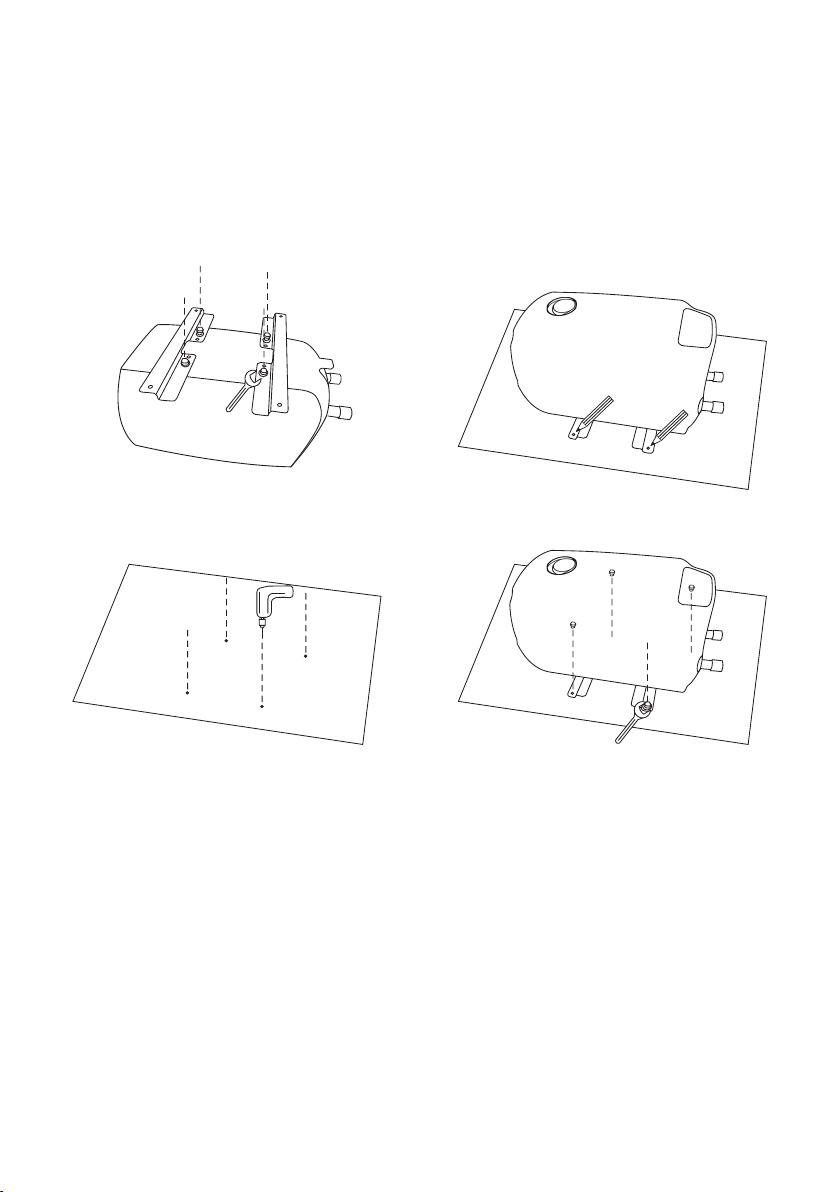
The caravan boiler must be mounted on a solid base plate with four
screws. Use suitable screws or other mounting systems for your base
plate. Optionally, the boiler can also be mounted vertically on a stable
wall.
1.
3. 4.
2.
Horizontal and vertical installation of the
photovoltaic boiler is possible.
• Relatively low heat losses
• 8 litres of hot water
• Slightly more heat loss
• 9.5 litres of hot water
The boiler was heated up to 65 °C. It was drained
at about 5 litres per minute. From a water tempe-
rature at the shower head of 35°C until the water
was 35°C again, the volume was measured.
1 2
1 2
3
4
5
5
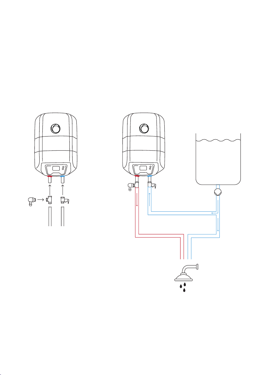
For safety reasons, the non-return/overpressure valve supplied must
be connected to the cold water inlet of the boiler.
The supplied drain plug must be connected to enable draining. This
can be done using the T-piece provided, as shown in Figure 1.
We recommend integrating the caravan boiler into a water system as
Water connection
Figure 1 Figure 2
EN
Valve + T-piece to be able to drain the boiler
2 Non-return / pressure relief valve
3 Water tank e.g. 40 litres
4 12 V pump (lying in the water if necessary).
Recommended pressure min. 0,75bar
5 Dusche/Waschbecken

6
The water in the boiler must not freeze. Frozen
water in the boiler can cause damage or a defect
in the appliance. If necessary, the contents of the
boiler can be drained via the non-return/overpres-
sure valve and the drain plug. Proceed as follows:
• Ensure that any water that leaks from the
non-return/overpressure valve and the drain
plug can drain away safely. This is important to
prevent possible water damage.
• Disconnect the water heater from any live
electrical wiring.
•
• Open the drain plug using the vent key provi-
ded.
• Tilt the small lever of the check/relief valve 90 °.
• The water should now drain away. Drainage is
complete when no more water comes out of
the valves.
• Small amounts of water remain in the boiler
cause any damage.
Drainage
The draining water can be hot - risk of scalding!
These steps do not ensure complete emptying of the water tank.
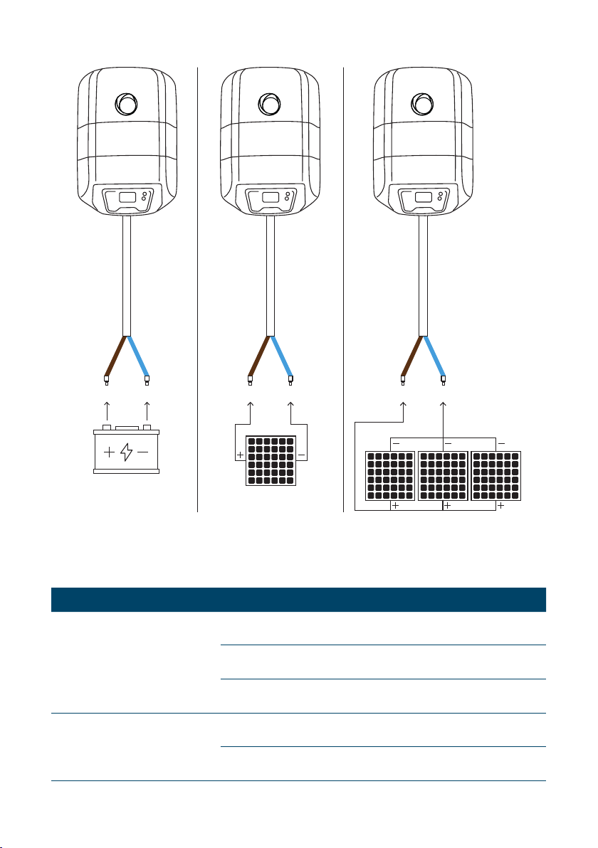
Source Voltage
PV module 0V–42.4V –
Battery 12 V, 24 V Lead acid, LiFePO4
External energy management 12V–42.4V –
EN
When connecting several photovoltaic modules,
these must only be connected in parallel.
7
Source Power hour
PV module
100W 9°C/h
300W 27°C/h
550W 47°C/h
Battery
12V (ca. 90 W) max. ~8°C/h
24V (ca. 350 W) max. ~32 °C /h
EN

8
button takes you to the next option
To change possible settings on an option page, such as
press the
Nr
1 Shows the water temperature in °C.
2POWER IN: Shows the instantaneous power consumption of the boiler.
VOLTAGE: Shows the current supply voltage of the boiler.
3 USED PV ENERGY: Displays the total PV energy consumed by the boiler.
4CHANGE MIN. TEMPERATURE: With the button you can change the minimum temperature.
This option interface is not available in all operating modes (see operating modes).
5CHANGE SYSTEM MODE: You can use the button to change the operating mode.
6
Figure 1
Figure 2
EN

9
1: PV Home PV module/
External energy
management
The boiler is heated with photovoltaic electricity. This mode
should be selected if there is an external energy management
(e.g. solar charge controller with deep discharge protection)
which releases the power for the boiler.
2: 12V Battery 12V Battery As soon as the battery reaches a voltage of 13.5V during the
charging process, the excess energy is used to heat up the
boiler.
3: 12V Battery
Reheat
12V Battery In addition to the excess control as in mode 2, the water is also
heated to this temperature again as soon as the set minimum
temperature is undershot. (But only until the maximum battery
voltage of 12.4 V is reached.)
4: 24V Battery 24V Battery As soon as the battery reaches a voltage of 27.0V during the
charging process, the excess energy is used to heat up the
boiler.
5: 24V Battery
Reheat
24V Battery In addition to the excess control as in mode 5, the water is also
heated up to this temperature again as soon as the set mini-
mum temperature is undershot. (But only until the maximum
battery voltage of 24.8 V is reached.)
EN
Be sure to carefully read the instructions and war-
nings in this manual before installing and operating
the water heater. The information contained in this
manual is intended to familiarize you with the water
heater, the rules of its correct and safe operation,
and the minimum requirements for its maintenance
and servicing. Furthermore, you are obliged to make
will install and potentially repair the appliance. The
of its functionality is not within the distributor's
warranty obligation nor the manufacturer.
These instructions should always be kept near the
appliance for future reference. Compliance with the
rules here described is part of the measures for the
safe use of the product and is considered part of the
warranty conditions.
WARNING!
There is a risk of burns or scalding when
using the appliance!
WARNING! This device can be used by children
from the age of eight and also by people with a lack
of experience and knowledge or reduced physical,
sensory or mental abilities, if they are supervised or
have been instructed in the safe use of the device
and understand the resulting dangers. Children
must not play with the device. Cleaning and user
maintenance shall not be made by children without
supervision.
IMPORTANT!
the water heater and connect it to the water pipe
the relevant local regulations. The protective devices
provided or recommended by the manufacturer, as
well as all other assemblies, are UNCONDITIONALLY
to be installed!

10
EN
IMPORTANT!
water before connecting it to the electrical sup-
ply! Failure to comply with the electrical connec-
whereby the water heater must not be operated.
IMPORTANT! Observe the maximum permissible
pressure (see chapter: Technical data).
• The device is under pressure. Expansion water
may drip out of the pressure relief valve during
heating.
• Operate the pressure relief valve regularly to
prevent it from getting stuck, e.g. B. to prevent
limescale deposits.
• Install a type-tested pressure relief valve in the
cold water supply line. Note that depending
on the pressure of the supply line, a pressure
reducer may also be required.
• Attach a drain line to the opening of the relief
valve, with an even slope to the drain.
• Dimension the drain line so that the water can
drain unhindered when the overpressure valve
is fully open.
• The opening of the pressure relief valve must
not be blocked.
• This device contains rechargeable batteries
which are not replaceable. However, their de-
fect does not limit the basic functionality.
• The device may be operated up to an altitude of
4000 m above sea level.
• The device owner is responsible for preventing
possible damage due to lightning strikes and
for proper installation of the PV modules with
lightning protection.
Technical data
This water heater can provide hot water from the
mains water supply or other pressure-operated
water supply for several consumers at the same
time. The water used for heating must meet the
requirements of the normative documents for ser-
vice water, in particular: chloride content up to 250
mg/l; electrical conductivity more than 100 µS/cm,
pH value 6.5 - 8 for hot water tanks with enamelled
water tank. The thermal insulation consists of CFC-
free polyurethane foam.
The maximum electrical output of the hot water sto-
rage tank is 550 W. The actual output of the heating
elements depends on both the connected photovol-
taic output and the intensity of the sun's radiation.
The water is heated to a maximum of 65 °C to ensure
protection against scalding. Detailed information
can be found on the data sheet or the nameplate.
The hot water storage tanks are equipped with a
combined non-return and pressure relief valve,
which prevents the water from being over-pressu-
rized while the device is in operation. The water
tanks are made of steel with a high-strength enamel
coating and additional cathodic protection with a
magnesium anode.
Always install the water heater lying down, in a dry
assembly as well as for the wall. Make sure that the
forces that act on the boiler or its mounting system
when driving. When choosing a suitable substrate
for the hot water storage tank, the following must
be taken into account:
• Type and material
• Dimensions of the device,
• Type of fastening
•
• Arrangement of water and electricity lines
• Degree of protection against water splashes
The installation site must comply with the requi-
rements of the water and electrical installation.
provided during installation.
attached mounting rails. Four screws are used for
this. The type, length and diameter of the screws
Autres manuels pour CPVB-10
2
Table des matières
Langues :
Autres manuels fothermo Chauffe-eau

fothermo
fothermo CPVB-10 Manuel utilisateur

fothermo
fothermo PVB-10 Manuel de la liste des pièces

fothermo
fothermo PSU-12 Manuel utilisateur

fothermo
fothermo PVB-30-AC Manuel utilisateur

fothermo
fothermo PVB-10 Manuel de la liste des pièces

fothermo
fothermo PVB-10 Manuel

fothermo
fothermo CPVB-10 Manuel utilisateur
Manuels Chauffe-eau populaires d'autres marques

Kenmore
Kenmore 153.582400 Manuel utilisateur

Applimo
Applimo Edel AIR Manuel utilisateur

STIEBEL ELTRON
STIEBEL ELTRON Eltronom SHU 5 S Manuel utilisateur

clage
clage E-Mini Series Manuel utilisateur

Toyotomi
Toyotomi Oil Miser OM-180 Manuel utilisateur

Bradford White
Bradford White EF Series Manuel utilisateur


 Guide de dépannage")


