Fixturlaser SMC Manuel utilisateur

USER MANUAL Fixturlaser SMC


USER MANUAL FIXTURLASER SMC, edition 1.3 (November 2017)
CONTENT
General presentation
1.1
General settings
2.1
Supervisor module
3.1
Balancing module
4.1
Maintenance
5.1
Technical specification
6.1


1.1
1 GENERAL PRESENTATION
1.1 INTRODUCTION
We want to congratulate you on your choice and hope that you will be fully satisfied with it. For this
reason, we recommend that you read carefully the present user guide and more specifically the safety
instructions.
Designed to meet industrial requirements for enhancing productivity, FIXTURLASER SMC is a portable
multichannel instrument coming along with a large touchscreen, a 3-axis wireless sensor and numerous
accessories. This innovative all-in-one solution makes vibration analysis available to all users.
FIXTURLASER SMC is available in 2 versions. The FIXTURLASER SMC standard (red rubber) is for
safe area, and the FIXTURLASER SMC-EX (black rubber) for ATEX Zone II area. Always refer to the
product marking to know which version you are using. All functionalities described in this manual are
applicable to both versions.
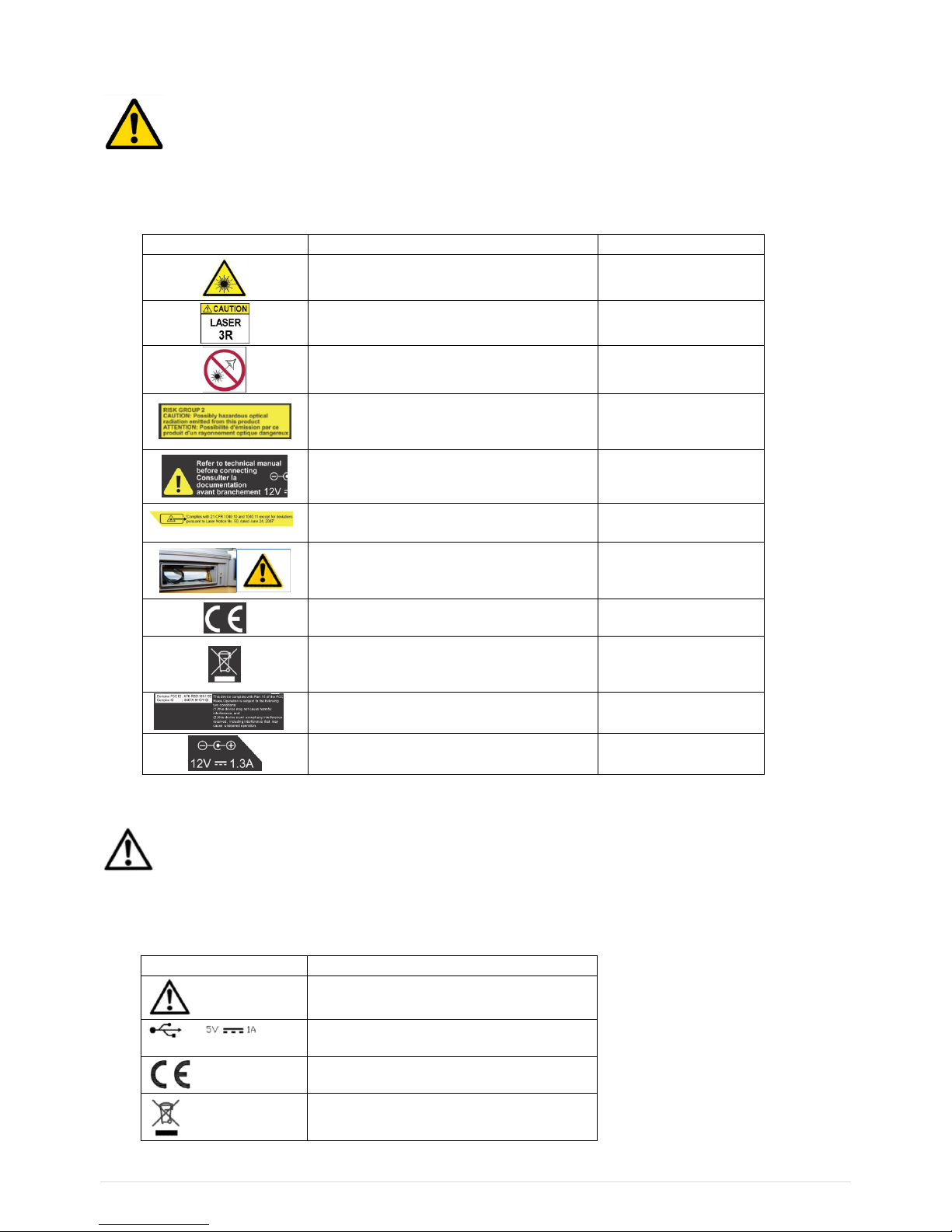
1.2 SAFETY INSTRUCTIONS
The safety instructions delivered with the instrument (printed and on the USB stick) should be carefully
followed and the instrument should always be used within the limits specified here.
Instrument and operator safety is at risk when the instrument is used in conditions that are not
intended by ACOEM.
Dismantling the instrument for an internal operation is forbidden. The only parts for which dismantling is
allowed are the battery hatch, the battery and the hatch providing access to the connectors.
All the spare parts must be provided by ACOEM.

1.2
List of symbols and warning on the instrument
Warning: Whenever this symbol is present on the device, refer to the safety instructions and user
manuals.
The table below lists the warning signs and security present on the instrument.
Symbol
Signification
Position
Laser radiation
Refer to section "Laser Class 3R"
Rear side (bottom)
Laser radiation class 3R
Refer to section "Laser Class 3R"
Rear side (bottom)
Avoid exposure to beam
Refer to section "Laser Class 3R"
Rear side (bottom)
Light Hazard Group 2
Refer to section "High-power white LED
flash and stroboscope"
Rear side (bottom)
Refer to the safety instructions
documentation and the user manual
before connecting
Rear side (bottom)
Laser aperture
Refer to section "Laser Class 3R"
Rear side (top)
Battery replacement
Refer to section "Battery pack set-up"
Battery compartment
CE certification data. Refer to the copy of
the CE APT2069 type certificate
Rear side (center)
Do not dispose of this product as unsorted
household waste.
Refer to section "Dismantling/recycling"
Rear side (center)
FCC and IC number. Refer to section
"Radio"
Rear side (center)
External power connection: refer to
section "Main Power supply block"
Rear side (bottom)
List of symbols and warning on WLS
Warning: Whenever this symbol is present on the device, refer to the safety instructions and user
manual.
The table below lists the warning signs and security present on the WLS sensor.
Symbol
Signification
Warning: Refer to the safety instructions
and user manuals
Use a power source with limited power
(=> Mains Power supply bloc)
=> CE certification data
=> Dismantling/recycling

1.3
Laser
Laser maintenance: The laser does not need maintenance or adjustment excluding cleaning the glass
with a cotton swab. Always shut off completely the device FIXTURLASER SMC before this operation.
Caution: Use of controls or adjustments or performance of procedures other than those specified herein
may result in hazardous radiation exposure.
Electric connections
All external circuits connected to the instrument must be non-hazardous voltage sources and be energy
limited as explained in sections 6.3 and 9.4 of the IEC61010-1 standard.
Do not exceed maximum input voltage on the A/B/C/D connectors: Maximum input voltage ±24 V DC,
±24 V AC peak.
All external circuits connected to the instrument must carry non-dangerous voltage as defined in
Standard IEC61010-1 (Paragraph 6.6)
Do not exceed maximum input voltage and current intensity for the power supply delivered by the mains
block (see chapter “Mains power block” of the safety instructions).
Use the cables designed for the different types of measurement.
If possible, protect the unused connectors using the plastic caps provided.

1.4
1.3 FIRST POWER UP
The instrument turns on automatically a few seconds after being connected to the mains through the
power supply module. If the battery level is too low, the charge starts and goes on as long as the
instrument is connected to its power supply.
When using a new battery, leave the battery in charge for about 10 hours in order to achieve full charge.
Do not use the instrument prior to 2-3 hours of charge. Usual charging time is about 6 hours when
instrument is switched off.
On-Off
•Power on: Press the On-Off key
•Power off: Press the On-Off key, then message “Shutdown”
Battery charge
•Power off: Press the On-Off key, then message “Shutdown”
•Connect the charger on the main. The instrument is automatically powered on. During the charge,
you can continue to use it. For a faster charge, it is recommended to switch-off the instrument. A full
charge requires about 6 hours.
It is recommended to disconnect the charger from the main when you are not using it.

1.5
1.4 USER INTERFACE
FIXTURLASER SMC starts on its “Home screen”. It is a touch screen and a simple pressure on it gives
access to the application modules installed on the instrument and to 2 side panels:
For more details:
•Supervisor module: See CHAPTER 3
•Balancing module: See CHAPTER 4
•Status panel: See § 1.9
•Shortcuts panel: See § 1.10
The 2 side panels are accessible from any screen.
Access to
application
modules
Access to
status side
panel
Access to
shortcuts side
panel

1.6
1.5 CONNECTIONS
Connectors A to D on the top of the instrument
Those connectors can be used in industrial environment. They are IP65
Connector A
Channels 1. Use this connector when the instrument is set in single-channel mode.
•Contact A:
•Contact B: Common
•Contact C: Channel 1 signal input
•Contact D:
•Contact E: Channel 3 signal input
•Contact F: -24 Vdc output
Connector B
Channels 2, 3 and 4. Use this connector with wired triaxial sensor when the instrument is set in multi-
channel mode.
•Contact A:
•Contact B: Common
•Contact C: Channel 2 signal input
•Contact D: Channel 3 signal input
•Contact E: Channel 4 signal input
•Contact F: -24 Vdc output
Notes
For 2-channel measurement, use connectors A and B
If inputs are set as IEPE, the sensor is powered by a 4 mA constant current. The integrity of the sensor
is monitored and a warning is issued if peak voltage is out of about 1 to 22 V.
A
B
C
D
Antenna for WLS
sensor and Wi-Fi
Table des matières
Autres manuels Fixturlaser Instrument de mesure
Manuels Instrument de mesure populaires d'autres marques

Endress+Hauser
Endress+Hauser Proline Promag 50 Caractéristiques techniques

Siemens
Siemens SITRANS F Coriolis FCT030 Manuel de la liste des pièces

KLINGER
KLINGER CMF V Series Manuel utilisateur

EXFO
EXFO FTB-2 Manuel d'exploitation et d'entretien

Keysight
Keysight M8290A Manuel utilisateur

ADTEK
ADTEK MW-5 Manuel utilisateur


