STEP 1 - PREPARE THE VEHICLE
Remove the negative terminal on the battery.
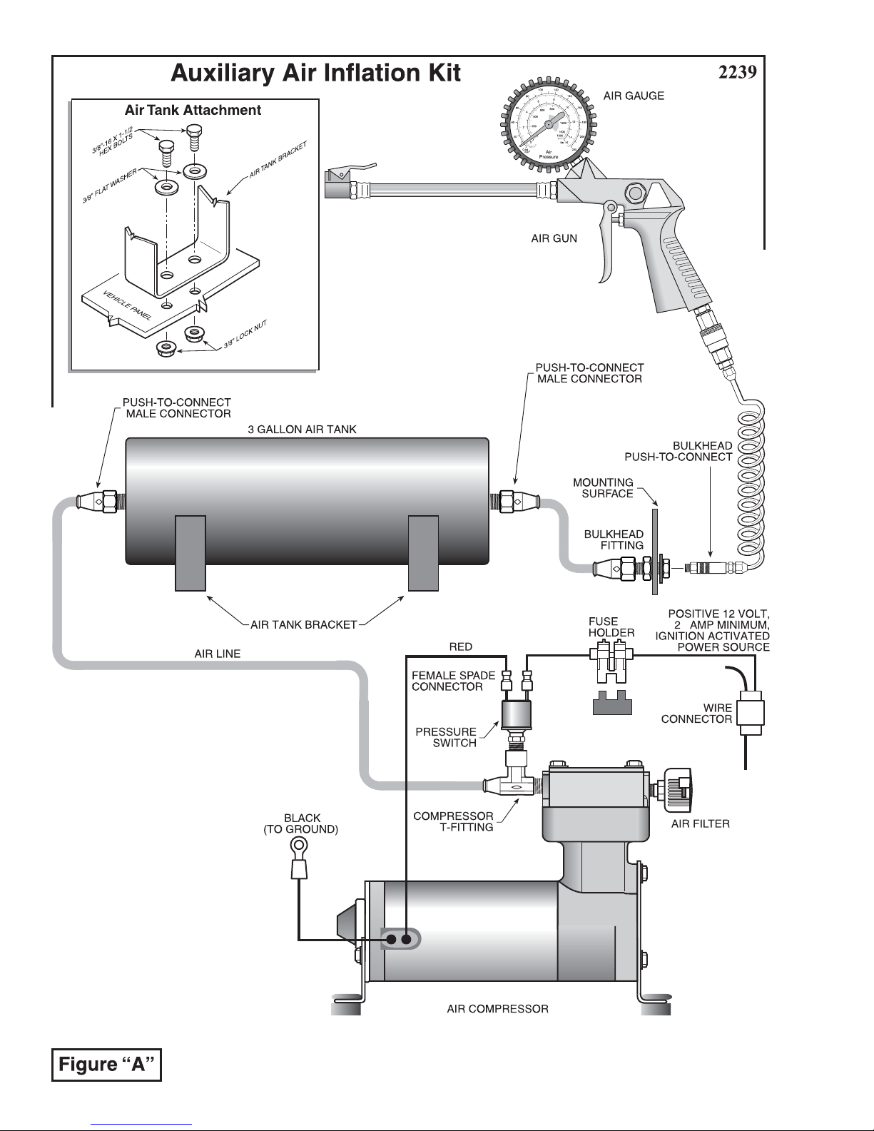
STEP 2 - PREPARE THE COMPRESSOR
Install the rubber isolator feet onto the compressor mounting
brackets. Insert the brass sleeves into the top of the isolator feet, see
Figure "B". Install the compressor T-fitting into the threaded
exhaust port on the compressor head, see Figure "A". Tighten the
fitting sufficiently to engage the pre-applied orange thread sealant.
(Torque to 40 in. lbs.) DO NOT OVERTIGHTEN THE FITTING.
InstallthepressureswitchintothecompressorT-fitting. Installtheair
filter into the threaded inlet port on the compressor head (finger
tight). Installthe positive(red) wirefrom thecompressor ontoeither
spade on the pressure switch, see Figure "A".
STEP 3 - MOUNT THE COMPRESSOR
Selectaconvenientlocationtomountthecompressor. Thislocation
shouldprovideampleairflowandbeprotectedfromairbornedebrisand
moisture. The mounting surface should be rigid to support the compressor, such as under the hood on a fender well
or in a vented storage compartment. The compressor is oil-less and can be mounted in any orientation necessary for
installation.
Usingthe compressor as a template, center punch, and drill three 3/16" holes. Before drilling, ensure that thereare
no electrical , fuel, or brake lines on the opposite side of the mounting surface that can be damaged by the drill. Any
burrsintheholesshouldberemovedtopreventdamagetotherubberisolators. Mountthecompressorusingthesupplied
10 -32 x 1" machine screws, 10 -32 lock nuts, and 3/16" washers. SeeFigure "B". Maximum vibration isolation can
be achieved by properly mounting the compressor. The machine screw and nut should be tightened only enough to
bottom-out the brass insert, see Figure "B". DO NOT OVERTIGHTEN. Overtightening will crush the brass insert
andtherubberisolator,thereby reducing vibrationisolation.
Attach the black wire from the compressor to a grounded component of the vehicle's chassis.
STEP 4 - MOUNT THE AIR TANK
Installthemalepush-to-connectfittingsintobothportsontheairtank. Tightenthefittingsufficientlytoengagethe
pre-appliedorangethreadsealant.Selectalocationtomounttheairtank. Thisshouldbeaprotectedlocationtoprevent
damagefromflyingrocksordebris. Usingtheholesinthetankbracketsasatemplate,markthelocationsofthemounting
holesonthemountingsurface.Useacenterpunchtomarkthecenteroftheholesonthemountingsurface.Beforedrilling,
ensurethattherearenoelectrical,fuel,orbrakelinesontheoppositesideofthemountingsurfacethatcanbedamaged
by the drill. Drill four 7/16" holes on the center marks. Using the supplied 3/8" hex bolts and flanged hex nuts, attach
theairtankintothemountingsurface.SeeFigure"A". Ensureclearaccesstothefittingsontheairtankismaintained.
Do not exceed 120 psi in the tank.
STEP 5 - MOUNT BULK HEAD FITTING
Installthebulkheadfittinginaconvienentprotectedlocation.Thelocationcouldbeanyrigidflatsurfacethatwould
beaccessibleforeasydischargeofairfortheenduser.Beforedrilling,ensurethattherearenoelectrical,fuel,orbrake
lines on the opposite side of the mounting surface that can be damaged by the drill. Mark and drill a 11/16" hole in the
desiredlocation.Installthebulkheadfittingandtighten,seeFigure"E". Installthe1/4NPTfittingonthecompressor
side of the bulk head fitting and tighten the fitting sufficiently to engage the pre-applied thread sealant. Install the dry
couplerfittingontheothersideofthebulkheadfittingandtightenthefittingsufficientlytoengagethepre-appliedsealant.
Figure "B"
BRASS SLEEVE
COMPRESSOR
FOOT
RUBBER
ISOLATOR
BRASS SLEEVE
COMPRESSOR
FOOT
RUBBER
ISOLATOR
#10 FLAT WASHER
#10 FLAT WASHER
VEHICLE
MOUNTING
SURFACE
#10 -32 LOCK
NUT
#10-32 x 1 PAN HEAD
SCREW