Fine Offset Electronics WH0280 Manuel utilisateur

Instruction Manual
1
Wireless Thermo-Hygro Monitor
Model: WH0280
Content
1. Introduce................................................................................................... 2
2. Get Started................................................................................................ 2
2.1 Package Contents......................................................................... 2
2.2Recommend Tools.......................................................................... 2
2.3 Thermometer Sensor Set Up....................................................... 2
2.4 Display Console Set Up................................................................ 4
3. Wireless Sensor Installation................................................................... 6
3.1 Mounting with Zip Tie.................................................................... 7
4. Console Operation................................................................................... 7
4.1 Key function.................................................................................... 7
4.2.Normal model................................................................................. 8
4.3 Time alarm model.......................................................................... 9
4.4Min value model.............................................................................. 9
4.5Max value model........................................................................... 10
4.6 Setting model ............................................................................... 11
4.7. Setting model for alarm clock ................... 错误!未定义书签。
5.Sensor Resynchronization..................................................................... 10
6.Best Practices for Wireless Communication....................................... 10
7.Specifications .......................................................................................... 12
7.1.Wireless Specifications............................................................... 12
7.2Measurement Specifications....................................................... 12
7.3Power Consumption..................................................................... 12
8. Troubleshooting Guide.......................................................................... 13

Instruction Manual
2
1. Introduce
Thank you for your purchasing of this Wireless Indoor/Outdoor
Thermometer with indoor humidity. To ensure the best product
performance, please read this manual and retain it for future
reference.
2. Get Started
Note: The power up sequence must be performed in the order shown
in this section: insert batteries in the remote sensor first, display
console second.
The weather station consists of a display console (receiver), and up to
3 thermometers (remote sensors), based on your order configuration.
2.1Package Contents
QTY
Item
1
Display Console
1
Remote sensor
1
Instruction Manual
2.2 Recommend Tools
Hammer for hanging remote thermometer transmitter.
2.3 Thermometer Sensor Set Up
Note: Do not use rechargeable batteries. They tend to have a lower
operating voltage, do not have a wide temperature range, and do not
last as long as non-rechargeable batteries.
Instruction Manual
3
We recommend fresh alkaline batteries for outdoor temperature
ranges between -20°C and 60°C and fresh lithium batteries for outdoor
temperature ranges between -40 °C and 60 °C.
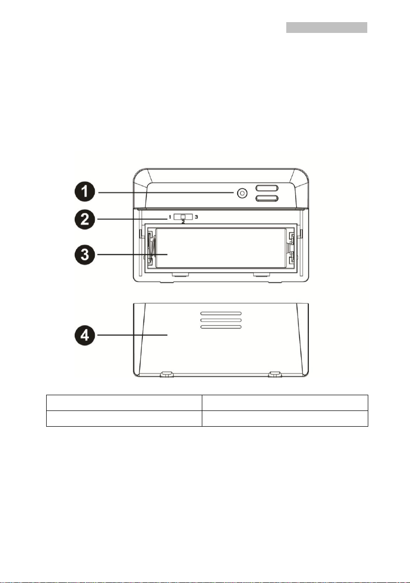
1. Remove the battery door on the back of the sensor by sliding the
compartment door down, as shown in Figure 1.
2. Set RF sensor channel.
Figure 1
1. LED indicator
2. RF channel 1,2,3
3. Battery compartment
4. Battery compartment door
3. Insert oneAA battery in the back of the sensor
4. After inserting the battery, the remote sensor LED indicator will light
for 4 seconds, and then flash once per 60 seconds thereafter. Each
time it flashes, the sensor is transmitting data.
5. Close the battery door.

Instruction Manual
4
2.4 Display Console Set Up
1. Move the remote thermometer(s) about 2 to 3m away from the
display console (if the sensor is too close, it may not be received
by the display console).
2. Remove the battery door on the back of the display. Insert one AA
(alkaline or lithium, avoid rechargeable) battery in the back of the
display console.
All of the LCD segments will light up for a few seconds to verify all
segments are operating properly.
Figure 2
1. Suspension eye for wall hanging
4. MODE key
2. Desk Stand
5. Battery Compartment
3. CH/+ key
6. Battery Compartment door
3. Replace the battery door, and fold out the desk stand and place
the console in the upright position.
The console will instantly display indoor temperature and humidity.
The remote temperature will update on the display within a few
minutes.

Instruction Manual
5
While in the search mode, the reception search icon flash.
Note: If the remote does not update, please reference the
troubleshooting guide in Section.
2.4.1 Display Console Layout
Figure 3
1.Time alarm Icon
5.Indoor Humidity
2.Indoor Temperature
6. Outdoor Reception Icon
3. Barometric Pressure graph
7. Outdoor Temperature
4 Time
2.4.2 Sensor Operation Verification
Verify the indoor and outdoor temperature match closely with the
console and sensor array in the same location (about 2 to 3m apart).
The sensors should be within 2°C (the accuracy is ± 1°C. Allow
about 30 minutes for both sensors to stabilize.

Instruction Manual
6
3. Wireless Sensor Installation
It is recommended you mount the remote sensor in a shaded area.
Direct sunlight and radiant heat sources will result in inaccurate
temperature readings. Although the sensor is water resistant, it is best
to mount in a well-protected area, such as under an eve.
3.1 Mounting with Zip Tie
Mounting the sensor with a zip tie will result in better accuracy when
mounting outside, since it is not touching other objects.
Figure 4
3.2 Mounting with Nail or screw
To mount the sensor with a nail or screw, the cap must be less than or
equal to 5mm in diameter.
Figure 5

Instruction Manual
7
4. Console Operation
The console has two buttons at the back of console for easy operation.
If no operation for 30s, display will return back to normal mode.
Key
Description
MODE
Press and hold to enter the Setting mode.
Press to switch between normal display mode,
time alarm mode and MIN/MAX mode.
CH/+
Hold both CH/+ and MODE to search the
sensor
Press to view the 3 sensor channel
While in MIN/MAX mode, press and hold to
reset the MIN/MAX value
While in SET mode, press to increase the
value. Press an hold to increase the value
rapidly.
There are five program modes available: Setting mode, Time Alarm
Mode, MIN/MAX Mode, Loop display Mode and Sensor Register Mode
4.1 Setting Mode
While in normal display, press the MODE key for 2 seconds to enter
Setting Mode
Press the MODE key to select the following settings in sequence:
1. 12/24 Hour format
2. Time setting (hour/minutes)
3. Temperature unit (°C / °F)
4. Complete setting mode and back to normal display

Instruction Manual
8
In the Set Mode, press CH/+ key to change or scrolls the value. Hold
the CH/+ key or or MODE key for 3 seconds will increase/decrease
digits in great steps.
4.2 Time Alarm Mode
While in normal display, short press the MODE key one time to enter
Time Alarm Mode
While in time alarm mode, press and hold the MODE key for 2
seconds, the alarm hour will begin flashing.
Change Alarm Hour. Press CH/+ key to adjust the alarm hour up.
Change Alarm Minute. Press the MODE key again to set the alarm
minute. Press CH/+ key to adjust the alarm minute. Press MODE key
again to confirm the setting.
Cancelling the alarm. When the alarm has been triggered, the alarm
will sound and the alarm icon will flash for 120 seconds. Press any

Instruction Manual
9
button to silence the alarm.
4.3 MIN/MAX mode
While in normal display, press the MODE key two times to enter the
Minimum mode, and the MIN icon and minimum records will be
displayed.
a. Select Channel display. If you have multiple temperature sensors,
press CH/+ to shift display Min value of Channel 1, 2 or 3. If there
is no extra outdoor sensor available, it will display --.—
b. Reset the Min value. Press and hold the CH/+ key to reset the
minimum value of indoor temperature, humidity and the current
display Min outdoor temperature to the current reading
While in normal display, press the MODE key three times to enter the
Maximum mode, and the MAX icon and maximum records will be
displayed.
a. Select Channel display. If you have multiple temperature sensors,
press CH/+ to shift display Max value of Channel 1, 2 or 3. If there
is no extra outdoor sensor available, it will display --.—
b. Reset the Max value. Press and hold the CH/+ key to reset the
maximum value of indoor temperature, humidity and the current

Instruction Manual
10
display Min outdoor temperature to the current reading
4.4 Loop display Mode
While in normal display, press the CH/+ key to select the outdoor
display in the following sequence:
CH1-CH2-CH3-
means to loop displays the current outdoor temperature value of
the RF channel automatically.
5.Sensor Resynchronization
If the remote sensor lost reception or extra sensors to be added, press
both the CH/+ and MODE keys at the same time for five seconds.
While in the search mode, the reception-search icon flash.
6. Best Practices for Wireless Communication
Note: To insure proper communication, mount the remote sensor on
a vertical surface, such as a wall. Do not lay the sensor flat.
Table des matières
Autres manuels Fine Offset Electronics Instrument de mesure


Manuels Instrument de mesure populaires d'autres marques


Endress+Hauser
Endress+Hauser Proline Promag 50 Caractéristiques techniques

Siemens
Siemens SITRANS F Coriolis FCT030 Manuel de la liste des pièces

KLINGER
KLINGER CMF V Series Manuel utilisateur

EXFO
EXFO FTB-2 Manuel d'exploitation et d'entretien

Keysight
Keysight M8290A Manuel utilisateur

ADTEK
ADTEK MW-5 Manuel utilisateur