
Field Controls 46086800 Manuel utilisateur
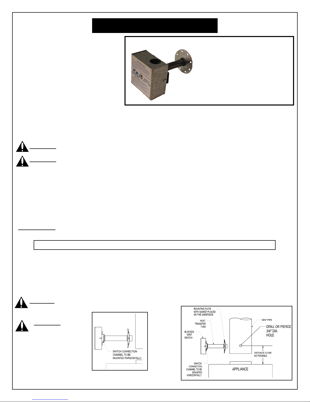
Figure 1
SEE THE APPLIANCE MANUFACTURER’S INSTRUCTIONS FOR THE SPECIFIC LOCATION.
IF THE APPLIANCE MANUFACTURER DOES NOT SPECIFY A LOCATION
,
REFER TO FIGURE 1.
BLOCKED VENT SWITCH
WARNING: Read the installation instructions carefully and completely before proceeding with the installation.
WARNING: Do NOT reset the device or restart the appliance unless the cause has been identified and corrected by
a qualified agency. Insure the switch appliance combination has been cleaned by a qualified agency before placing
back into service. Annual inspection and cleaning by a qualified agency is required.
• Wiring MUST be in accordance with the current Canadian Electric Code and any other applicable federal,
provincial and local code requirements.
• For installations in the USA, all wiring shall be in accordance with the National Electrical Code and applicable local
codes.
• For continued safe operation, the appliance-switch combination is required to be inspected and maintained annually
by a qualified agency. Failure to properly maintain the appliance-switch combination can lead to Death, Personal
Injury and or Property Damage.
INSTALLATION
MOUNTING IN THE VENT PIPE
1. Drill or pierce a clean hole (about 3/4” diameter) in the vent pipe near the appliance outlet. (See Figure 1)
2. The heat transfer tube must have the fiber gasket installed against the mounting plate before attaching the unit to the
vent pipe
3. Insert the heat transfer tube with gasket into the 3/4” diameter hole placed in the vent pipe during step 1.
4. Secure the assembly to the vent pipe with a minimum of 4 sheet metal screws. The channel must be mounted
horizontally, unless specified differently by the appliance manufacturer. (See Figure 1)
CAUTION: Disconnect electrical power supply to the appliance when wiring the blocked vent switch.
Model: WMO-1
The WMO-1 Blocked Vent Switch is
recommended for installation with an
oil fired appliance that normall
y
operates with its vent system under a
negative pressure. This device is
intended to detect a blocked ven
t
system, responds to hot flue gases
backing up through its heat transfe
r
tube, and can be wired to shut off the
oil burner. It requires manual resetting.
This device MUST be installed by a qualified agency* in accordance with the manufacturer’s installation instructions.
The definition of a qualified agency is: any individual, firm, corporation or company which either in person or through a
representative is engaged in, and is responsible for, the installation and operation of oil appliances, who is experienced
in such work, familiar with all the precautions required, and has complied with all the requirements of the authority
having jurisdiction.
WARNING:
Switch connection
channel must be
mounted horizontally,
unless specified
differently by the
appliance manufacturer.
ITEMS SUPPLIED IN THIS KIT:
1-Blocked vent switch assembly
1-Gasket
1-Instruction sheet

FOLLOW THE APPLIANCE MANUFACTURER’S WIRING DIAGRAM.
IF THE APPLIANCE MANUFACTURER DOES NOT SUPPLY A WIRING DIAGRAM
,
REFER TO DIAGRAMS A OR B.
DO NOT DENT OR SCRATCH THE SURFACE OF THE THERMAL SWITCH.
IF THE THERMAL SWITCH IS DAMAGED, REPLACEMENT IS REQUIRED.
WIRING INSTRUCTIONS
5. Wire the blocked vent switch in
series with the limit control circuit to
the primary control or as an optional
location in series with the orange
wire from the primary control to the
burner motor. (See Diagram A and
B) Route all wiring with an
acceptable wiring enclosure in
accordance with the current CSA
C22.1 Canadian Electric Code
Part 1 and any other applicable
federal, provincial and local code
requirements. For installations in the
USA all wiring shall be in accordance
with the National Electrical Code
and applicable local codes.
6. The following are typical wiring
diagrams. Read and follow the
appliance manufacturer’s instructions
and wiring diagram.
MAINTENANCE:
Note: For continued safe operation, the appliance-switch
combination is required to be inspected and maintained annually by
a qualified agency.
7. Disconnect power to the appliance.
8. Remove the two screws holding on the WMO-1 blocked vent
switch assembly cover.
9. Remove the cover.
10. Remove the two screws holding the control box to the heat
transfer tube assembly. The control box slides, unlocking it
from the heat transfer tube assembly.
11. Carefully remove any buildup from the thermal switch surface.
12. Clear and remove any buildup or obstruction inside the heat
transfer tube.
13. Remount, lock and refasten the control box with the two screws
removed in step 10.
14. Reattach the assembly cover with screws removed in
step 8.
15. Re-establish power to the appliance.
Diagram A
Honeywell R7184B & Carlin 60200-02
Diagram B
Riello
CURRENT RATING
120 VAC 10 FL AMPS 60 LR AMPS
240 VAC 5 FL AMPS 30 LR AMPS

Figure 1
VOIR INSTRUCTIONS DU FABRICANT DE L’APPAREIL POUR CONNAITRE L’EMPLACEMENT SPÉCIFIQUE.
SI LE FABRICANT DE L’APPAREIL NE SPÉCIFIE PAS D’EMPLACEMENT, CONSULTER LES FIGURE 1.
COMMUTATEUR POUR VENTILATION BLOQUÉE
AVERTISSEMENT : Lire attentivement et intégralement les instructions relatives à l’installation avant d’entreprendre
l’installation.
AVERTISSEMENT : NE PAS réinitialiser le dispositif ou remettre l’appareil en marche avant d’avoir identifié la cause
et de l’avoir faite rectifier par une agence qualifiée. S’assurer que la combinaison commutateur-appareil a été
nettoyée par une agence qualifiée avant la remise en service. Une agence qualifiée doit procéder à une inspection et
un nettoyage annuels.
• Le câblage DOIT être conforme aux exigences en cours du Code canadien de l’électricité et de tout autre code
en vigueur aux niveaux fédéral, provincial et local.
• Pour les installations aux États-Unis, tout le câblage sera conforme au Code national de l’électricité et aux codes
locaux en vigueur.
• Pour un fonctionnement continu en toute sécurité, la combinaison appareil-commutateur doit faire l’objet d’une
inspection et d’un entretien, une fois par an, par une agence qualifiée. Un mauvais entretien de la combinaison
appareil-commutateur peut entraîner la mort, des blessures corporelles et/ou des dégâts matériels.
INSTALLATION
MONTAGE DANS LE TUYAU DE VENTILATION
1. Percer un trou net [d’environ 1,9 cm (3/4") de diamètre] dans le tuyau de ventilation à proximité de la prise de
l’appareil. (Voir figure 1.)
2. Le tube de transfert thermique doit être muni d’un joint en fibre installé contre la plaque de fixation avant d’attacher
l’unité au tuyau de ventilation.
3. Insérer le tube de transfert thermique avec le joint dans le trou de 1,9 cm (3/4") de diamètre placé dans le tuyau de
ventilation à l’étape 1.
4. Fixer l’ensemble au tuyau de ventilation avec au moins 4 vis auto-taraudeuses. Le canal doit être monté
horizontalement, à moins que ce ne soit indiqué différemment par le fabricant d'appareils. (Voir figure 1.)
ATTENTION : Débrancher toute alimentation électrique à l’appareil lors du câblage du commutateur pour
ventilation bloquée.
Modèle : WMO-1
Il est recommandé d’installer le commutateu
r
pour ventilation bloquée WMO-1 avec un
appareil au mazout qui fonctionne
normalement avec son système de ventilation
sous dépression. Ce dispositif est prévu pou
r
détecter un système de ventilation bloqué,
pour répondre aux gaz de cheminée chauds
se formant dans son tube de transfert
thermique et pouvant être câblé pour éteindre
le brûleur à mazout. Il doit être réinitialisé
manuellement.
Ce dispositif DOIT être installé par une agence qualifiée* conformément aux instructions d’installation du fabricant.
Par agence qualifiée, on entend : tout individu, toute firme, toute corporation ou toute société qui, soit en personne soit par le biais
d’un représentant, engagé dans et responsable de l’installation et du fonctionnement des appareils au mazout, ait une expérience
dans ledit domaine, connaisse toutes les précautions requises et respecte toutes les exigences de l’autorité ayant juridiction.
AVERTISSEMENT :
Le canal de connexion
de commutateur doit
être monté
horizontalement, à
moins que ce ne soit
indiqué différemment
par le fabricant
d'appareils.
ARTICLES FOURNIS DANS CE KIT :
1-Ensemble de commutateur pour
ventilation bloquée
1-Joint
1-Fiche d’instructions

SUIVRE LES INSTRUCTIONS DU SCHÉMA DE CABLAGE DU FABRICANT DE L'APPAREIL.
SI LE FABRICANT DE L'APPAREIL NE FOURNIT PAS DE SCHÉMA DE CABLAGE
,
CONSULTER LE SCHÉMA A OU B.
NE PAS BOSSELER NI RAYER LA SURFACE DU COMMUTATEUR THERMIQUE.
SI LE COMMUTATEUR THERMIQUE EST ENDOMMAGÉ, IL FAUT LE
REMPLACER.
INSTRUCTIONS RELATIVES AU CABLAGE
5. Câbler le commutateur pour ventilation
bloquée en série, le circuit limiteur à
l’appareil de commande ou comme
emplacement facultatif en série avec le
fil orange de l’appareil de commande
au moteur du brûleur. (Voir Schémas A
et B.) Acheminer tout le câblage muni
d’une gaine de câble acceptable
conformément aux exigences en cours
de la norme CSA C22.1 Code
canadien de l’électricité Partie 1 et de
tout autre code en vigueur aux niveaux
fédéral, provincial et local. Pour les
installations aux États-Unis, tout le
câblage sera conforme au Code
national de l’électricité et aux codes
locaux en vigueur.
6. Les schémas suivants sont des
schémas de câblage types. Lire et
suivre les instructions et le schéma
de câblage du fabricant de l’appareil.
ENTRETIEN :
Remarque :Pour un fonctionnement continu en toute sécurité, la
combinaison appareil-commutateur doit faire l’objet d’une inspection et
d’un entretien, une fois par an, par une agence qualifiée.
7. Débrancher toute alimentation à l’appareil.
8. Dévisser les deux vis qui maintiennent le couvercle de l’ensemble
de commutateur pour ventilation bloquée WMO-1.
9. Retirer le couvercle.
10. Retirer les deux vis qui maintiennent le boîtier de commande à
l’ensemble du tube de transfert thermique. Le boîtier de commande
coulisse, en le débloquant de l’ensemble du tube de transfert
thermique.
11. Retirer avec soin tout dépôt de la surface du commutateur
thermique.
12. Dégager et éliminer tout dépôt ou toute obstruction à l’intérieur du
tube de transfert thermique.
13. Remonter, verrouiller et refixer le boîtier de commande à l’aide des
deux vis qui avaient été retirées à l’étape 10.
14. Remonter et fixer le couvercle de l’ensemble à l’aide des
vis qui avaient été retirées à l’étape 8.
15. Rebrancher toute alimentation à l’appareil.
TERRE DE
L’ÉQUIPEMENT
NOIR : CARLIN
ROUGE/BLANC : CARLIN
VIS DE
TERRE
FIL DE DÉMARRAGE DE 120
V c.a. DU BRÛLEUR, À
PARTIR DE L’APPAREIL
(DU CIRCUIT DU LIMITEUR)
PRIMAIRE
WMO-1
ROUGE
NOIR
BLANC
LIMITEUR
L1 (CHAUD)
L2 (NEUTRE)
120 V c.a.
DE
L’APPAREIL
VERS LE CIRCUIT À DISTANCE DE
L’ALARME c.a. DE FAIBLE TENSION (SI
UTILISÉ)
SUR CERTAINS MODÈLES
SOUPAPE DE
MAZOUT
ALLUMAGE
MOTEUR DU
BRÛLEUR
CELLULE
AU CdS
WMO-1
MAUVE
BLEU
ORANGE
JAUNE
JAUNE
SOUPAPE
ALLUMAGE
MOTEUR
CELLULE
AU CdS
CELLULE
AU CdS
COMMANDE
PRINCIPALE
THERMOSTAT
DE 24 V c.a.
EN OPTION
Schéma A
Honeywell R7184B et Carlin 60200-02
120 V c.a. DU CIRCUIT
LIMITEUR OU DE
L’AQUASTAT
(NEUTRE) (CHAUD)
TERRE (VERT)
COMMUN (BLANC)
LIGNE SOUS TENSION
(NOIR)
FUSIBLE 15 A
CONTACTEUR DE SÉCURITÉ
DE LIGNE
CONTACTEUR DE LIMITEUR EN
FONCTIONNEMENT
CONTACTEUR DE LIMITEUR DE
SÉCURITÉ PRIMAIRE
WMO-1
SOUPAPE
BLEU
BRUN
NOIR
BLEU
BRUN
BLANC
NOIR
MOTEUR
CONDENSATEUR
BO
Î
TIER DE COMMANDE DU
BRÛLEUR, CÂBLÉ À L’USINE
Schéma B
Riello
COURANT NOMINAL
120 c.a. 10 FL A 60 LR A
240 c.a. 5 FL A 30 LR A
P/N 46086800 Rev D 07/06
2630 Airport Road, Kinston, NC 28504
www.fieldcontrols.com
For Technical Support
call…
1-800-742-VENT
Pour le service technique,
appeler …
1 800 742-VENT
Ce manuel convient aux modèles suivants
1
Table des matières
Langues :
Autres manuels Field Controls Changer

Field Controls
Field Controls WMO-1 Manuel utilisateur

Field Controls
Field Controls 46178400 Manuel utilisateur

Field Controls
Field Controls 46149200 Manuel utilisateur
Field Controls
Field Controls 46170300 Instructions de montage

Field Controls
Field Controls 46104600 Manuel utilisateur

Field Controls
Field Controls GSK-160A Manuel utilisateur

Field Controls
Field Controls 46126500 Manuel utilisateur

Field Controls
Field Controls 46114900 Manuel utilisateur

Field Controls
Field Controls WMO-1 Manuel utilisateur

Field Controls
Field Controls 46457600 Manuel d'exploitation et d'entretien


