FibroLAN Falcon-MX/G/428/A Fiche technique

Falcon
Product Technical Note
PTP Grandmaster Configuration
Profiles: G.8275.1, G.8257.2, G.8265.1

T e c h N o t e : P T P G r a n d m a s t e r C o n f i g u r a t i o n
2 | P a g e
Administrative Information
Applicable models
Part Number
Applicable software version
Falcon-MX/G/428/A
7122
7.4.22 and above
Falcon-MX/G/428/D
7123
7.4.22 and above
µFalcon-MX/G
7143
7.4.22 and above
Document Management
Document Type
Technical Note
Source File Name
Fibrolan-TN_GM_PTP_Configuration_V1.4-2021-04-02.Docx
Created
Document version
Date
Idan Reshef
1.4
02/04/2021
Modified
Document version
Date
Proprietary Information. This document contains information, which is proprietary to Fibrolan
Ltd. No part of its contents may be used, copied, disclosed or conveyed to a third party in any
manner whatsoever without prior written permission from Fibrolan Ltd.
www.fibrolan.com
T e c h N o t e : P T P G r a n d m a s t e r C o n f i g u r a t i o n
3 | P a g e
PTP Grandmaster Configuration
This guide briefly describes how to configure Falcon-MX/G and µFalcon-MX/G to operate as a
PTP Grandmaster in compliance with ITU-T G.8275.1, G.8275.2 and G.8265.1 profiles. To
properly source and propagate timing signal the µFalcon-MX/G must first be installed and
connected to a GNSS antenna (for details on antenna installation refer to Technical Note:
GPS/GNSS Antenna Installation Guidelines on www.fibrolan.com Resources webpage).
1Physical Description
The M Class Falcon /G models are high-performance Carrier Ethernet switches, which includes
highly comprehensive Timing and Synchronization capabilities. The M Class Falcon Grandmaster
models are available in two form factors:
•Falcon-MX/G: 19” 1RU size
•µFalcon-MX/G: ½ 19” 1RU size
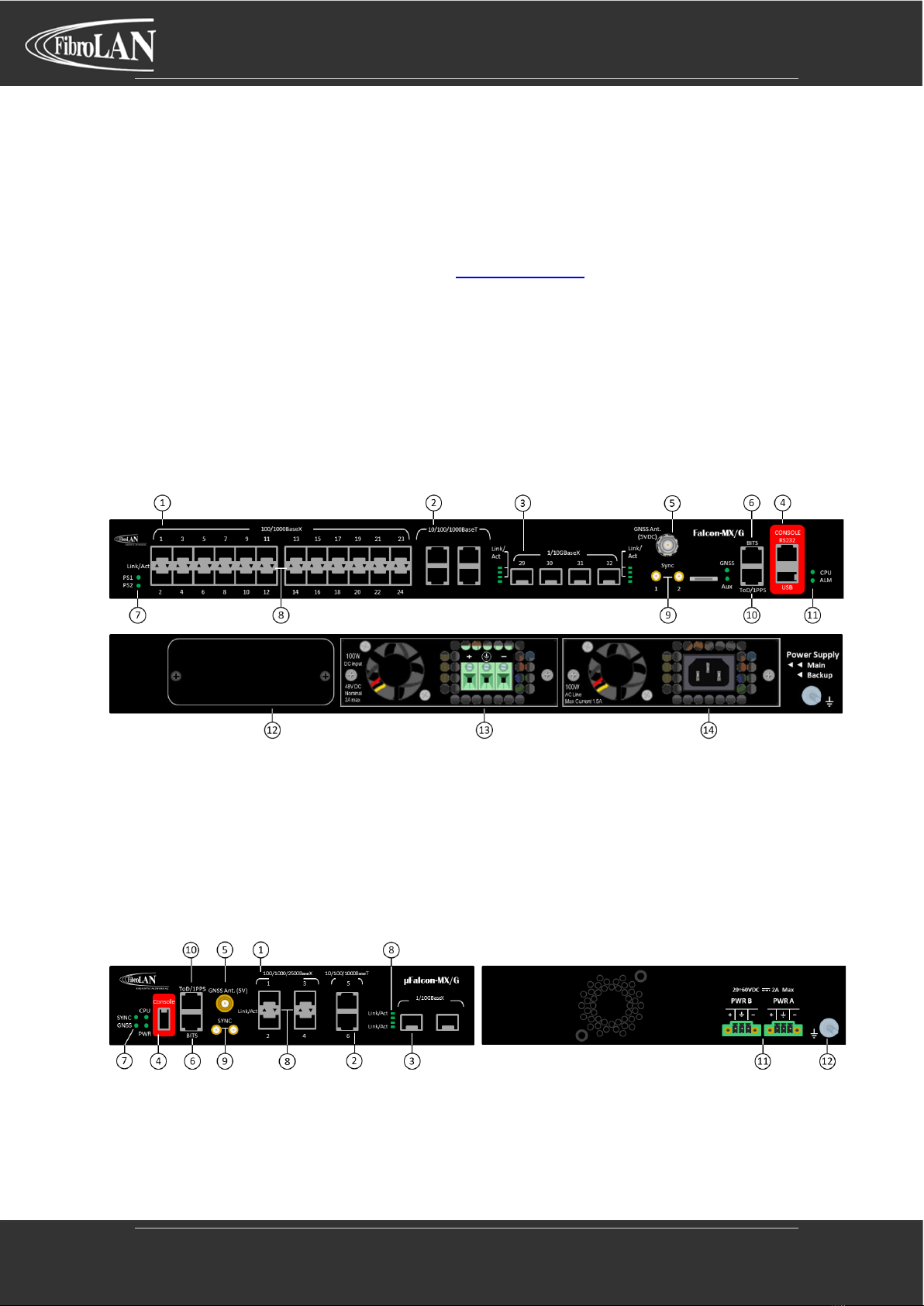
1.1 Falcon-MX/G
①
24x 100/1000 BaseX
⑧
LEDs indicators Link/Activity (per port)
②
4x 10/100/1000 BaseT
⑨
2x Sync SMA input/output –1PPS/10 MHz
③
4x 1/10G BaseX
⑩
RJ45 input/output ToD/1PPS
④
RJ45 and USB Console
⑪
LEDs indicators CPU/Alarm
⑤
GNSS antenna TNC connector (5VDC)
⑫
Expansion module for Rubidium clock
⑥
1.5 / 2 Mbps BITS input/output
⑬
PSU1 –AC/DC options supported
⑦
LEDs indicators PSU1/PSU2
⑭
PSU2 –AC/DC options supported
1.2 µFalcon-MX/G
①
4x 100/1000 BaseX
⑦
LEDs indicators Power/CPU/Sync/GNSS
②
2x 10/100/1000 BaseT
⑧
LEDs indicators Link/Activity (per port)
③
2x 1/10G BaseX
⑨
2x Sync SMA input/output –1PPS/10 MHz
④
USB Console
⑩
RJ45 input/output ToD/1PPS
⑤
GNSS antenna TNC connector (5VDC)
⑪
Dual 20÷60 VDC inputs
⑥
1.5 / 2 Mbps BITS input/output
⑫
Ground

T e c h N o t e : P T P G r a n d m a s t e r C o n f i g u r a t i o n
4 | P a g e
2Configuration Steps
2.1 Initial Settings
Before starting with the Timing configuration ensure proper management access via web GUI.
Detailed information on system turnup can be found in the Falcon M class Getting Started quick
guide that can be found in www.fibrolan.com.
2.2 GPS/GNSS Signal
Additional prerequisite is to assure a proper satellite signal. To do that hit the GPS/GNSS port
on the front panel at the GUI home page. This will lead to the GPS/GNSS monitor screen.
Verify the GPS/GNSS module is locked on the incoming signal, no alarms are present and there
is good visibility of satellites in the sky.
2.3 Setting up the SyncCenter
•Hit the SyncCenter button at the GUI top right corner.
•In the SyncCeter page enable source 1 and set it to GPS, as shown below, then press the
Apply at the bottom of the page.

T e c h N o t e : P T P G r a n d m a s t e r C o n f i g u r a t i o n
5 | P a g e
3PTP Configuration
3.1 G.8275.1 Profile
This Precision time protocol telecom profile is intended for phase/time synchronization with full
timing support network. This is an Ethernet multicast profile (layer 2 transport)
•Hit the PTP link from the left side menu: Configuration>Timing>PTP
•Create a new PTP Clock instance and set it to Masteronly type and G.8275.1 Profile.
•Follow the hyperlink of the instance number to the next configuration page.
•Enable the relevant physical interface by checking the checkboxes of the relevant ports.
Notes:
1. G.8275.1 profile default settings are:
•Transport layer: Ethernet
•PTP Domain number: 24
•Message frame rates:
oAnnounce: (-3) or 8/sec
oSync: (-4) or 16/sec
oDelay Response: (-4) or 16/sec
2. Message frame rates can be modified by pressing the “Ports Configuration” link if needed.
3. This profile uses Multicast transmission, packets will be sent on any enabled port, regardless
of whether there is a slave connected to it or not.

T e c h N o t e : P T P G r a n d m a s t e r C o n f i g u r a t i o n
6 | P a g e
•Apply the configuration by pressing the Apply at the bottom of the page.
3.2 G.8275.2 Profile
This Precision time protocol telecom profile is intended for phase/time synchronization with
partial timing support network. This is an UDP/IP unicast profile (layer 3 transport)
•Hit the PTP link from the left side menu: Configuration>Timing>PTP
•Create a new PTP Clock instance and set it to Masteronly type and G.8275.2Profile.
•Follow the hyperlink of the instance number to the next configuration page.
•Enable the relevant physical interface by checking the checkboxes of the relevant ports.
Notes:
1. G.8275.2 profile default settings are:
•Transport layer: IPv4 Unicast
•PTP Domain number: 44
•Message frame rates:
oAnnounce: (-3) or 8/sec
oSync: (-7) or 128/sec
oDelay Response: (-7) or 128/sec
2. In unicast profiles message rates are requested by slave device in dedicated signaling
3. Maximum message rates can be enforced on the Grandmaster per port by pressing the
“Ports Configuration”.

T e c h N o t e : P T P G r a n d m a s t e r C o n f i g u r a t i o n
7 | P a g e
•Apply the configuration by pressing the Apply at the bottom of the page.
3.3 G.8265.1 Profile
This Precision time protocol telecom profile is intended for frequency synchronization. This is
an UDP/IP unicast profile (layer 3 transport)
•Hit the PTP link from the left side menu: Configuration>Timing>PTP
•Create a new PTP Clock instance and set it to Masteronly type and G.8265.1Profile.
•Follow the hyperlink of the instance number to the next configuration page.
•Enable the relevant physical interface by checking the checkboxes of the relevant ports.
Notes:
1. G.8265.1 profile default settings are:
•Transport layer: IPv4 Unicast
•PTP Domain number: 4
•Message frame rates:
oAnnounce: (-3) or 8/sec
oSync: (-7) or 128/sec
oDelay Response: (-7) or 128/sec
2. In unicast profiles message rates are requested by slave device in dedicated signaling
3. Maximum message rates can be enforced on the Grandmaster per port by pressing the
“Ports Configuration”.

T e c h N o t e : P T P G r a n d m a s t e r C o n f i g u r a t i o n
8 | P a g e
•Apply the configuration by pressing the Apply at the bottom of the page.
•Save the configuration by hitting the Save button at the GUI top left corner.
Notes:
1. All Ethernet ports (1-24 and 29-32 on Falcon, 1-8 on µFalcon models) support PTP and SyncE
simultaneously
2. Falcon-MX/G copper port (25-28) are management ports and do not support PTP nor SyncE.
3. Internal ports (33-37 on Falcon, 9-11 on µFalcon models) may be ignored.
4. The default parameters of the profile may be modified as needed (but take care to avoid
misconfiguration)
5. If needed PTP messages can be tagged by setting the port mode to Trunk
6. For more complex or atypical configurations, please Contact Us.

T e c h N o t e : P T P G r a n d m a s t e r C o n f i g u r a t i o n
9 | P a g e
We’ve got Timing for you!
Intl. Headquarters
Fibrolan Ltd.
Tel: +972-4-959-1717
Fax: +972-4-959-1718
www.fibrolan.com
North America
Fibrolan Inc.
Tel: +1-201-843-1626
Fax: +1-201-843-1628
www.fibrolan.com
Central-Eastern Europe
Fibrolan CEE GmbH.
Tel: +43-2253-21188-88
Fax: +43-2253-21188-99
www.fibrolan.at
©2020 Fibrolan. All Rights Reserved
Ce manuel convient aux modèles suivants
5
Table des matières
Autres manuels FibroLAN Matériel réseau

Manuels Matériel réseau populaires d'autres marques

Matrix Switch Corporation
Matrix Switch Corporation MSC-HD161DEL Manuel utilisateur

B&B Electronics
B&B Electronics ZXT9-IO-222R2 Manuel utilisateur

Yudor
Yudor YDS-16 Manuel utilisateur

D-Link
D-Link ShareCenter DNS-320L Manuel utilisateur

Samsung
Samsung ES1642dc Instructions d'utilisation

Honeywell Home
Honeywell Home LTEM-PV Instructions de montage


